
Switching device for achieving switching control over multiple power systems

A switching device and power system technology, applied in circuit devices, emergency power supply arrangements, electrical components, etc., can solve the problems of secondary short circuit, unable to meet the requirements of sensitive load system power switching speed, etc., to achieve compact structure and increase anti-interference. The effect of overcoming the trouble of wiring

Active Publication Date: 2014-04-30
SHENZHEN TAIYONG ELECTRICAL TECH
View PDF5 Cites 5 Cited by
  • Summary
  • Abstract
  • Description
  • Claims
  • Application Information

AI Technical Summary

Problems solved by technology

For loads that are not allowed to be powered off, power switching needs to be completed within 20 milliseconds or even 4 milliseconds. Therefore, traditional mechanical switches or relays cannot meet the requirements of sensitive load systems for power switching speed
Moreover, the traditional mechanical type will generate arcing during the switching process, and the circulation caused by the arcing will easily cause secondary short circuit

Method used


Image

  • Switching device for achieving switching control over multiple power systems
  • Switching device for achieving switching control over multiple power systems
  • Switching device for achieving switching control over multiple power systems

Examples


Embodiment Construction

[0031] First of all, all embodiments of the present invention are described by taking three-phase dual power supplies as an example. The two power supplies are respectively the main power supply and the standby power supply. It should be understood that when the number of power supplies is greater than two The structure of the switching device for switching control of the power system is similar to it and will not be repeated here.

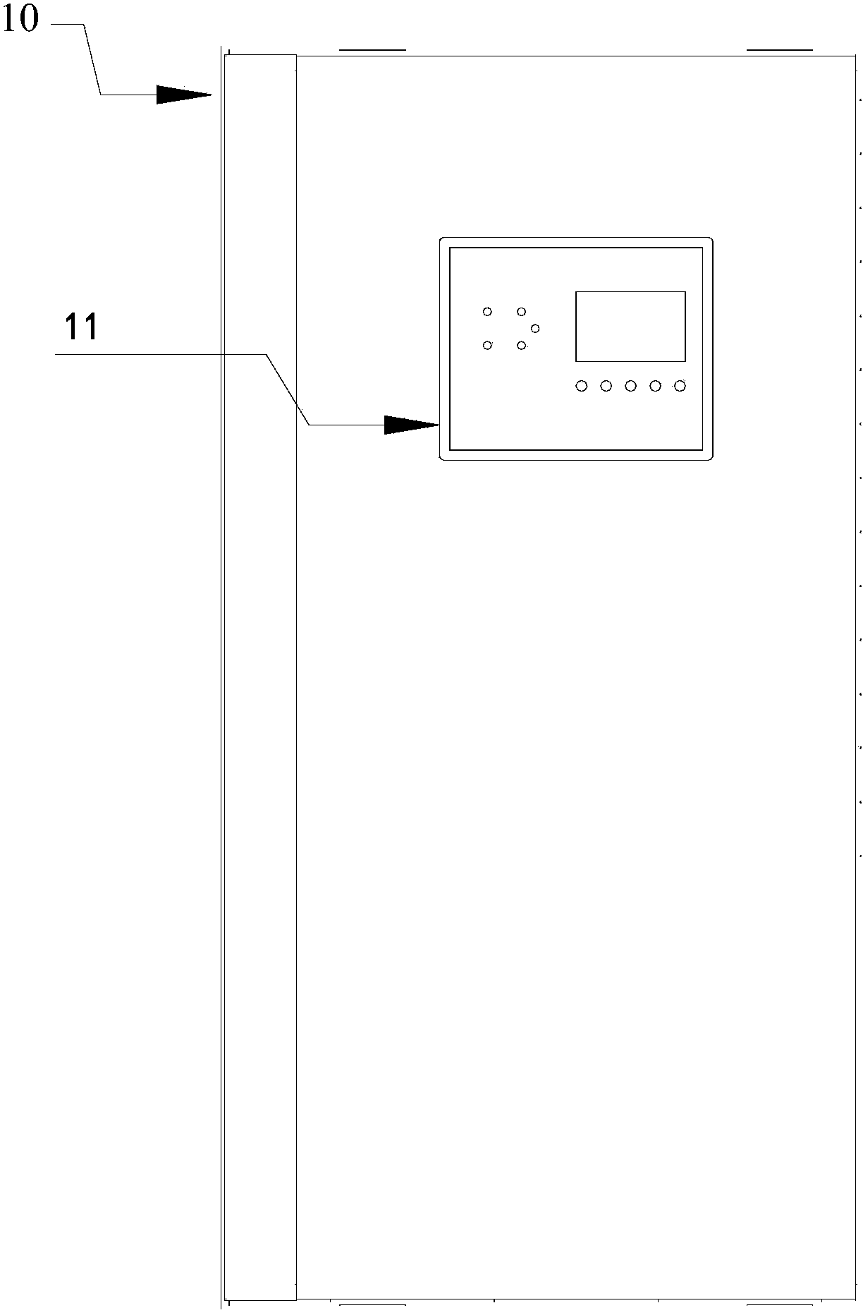
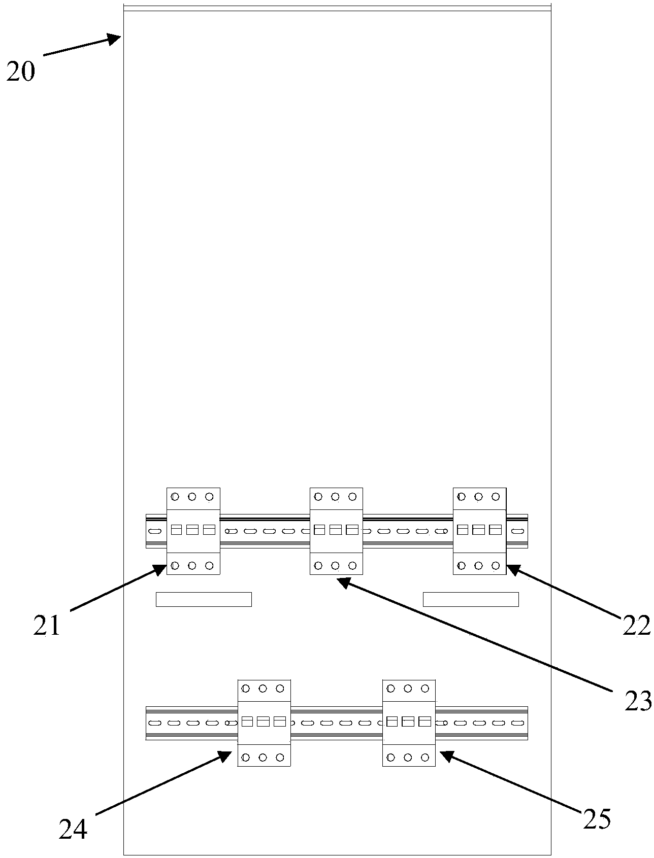
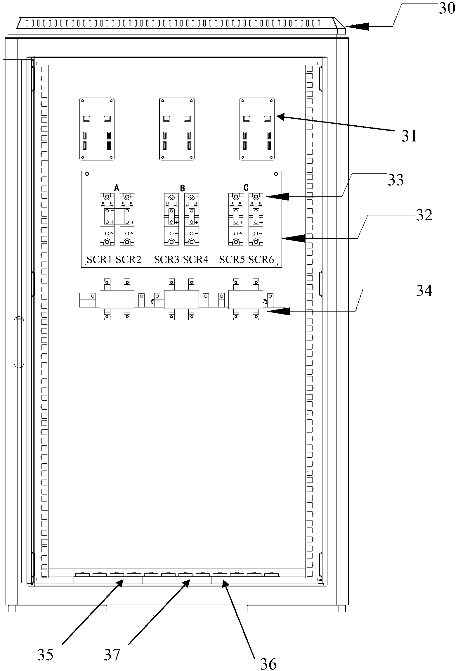
[0032] combine Figure 1-3, the switchgear used to realize the switching control of the dual power supply system includes a connected cabinet body 30 and a cabinet door. Main controller 11 is arranged on it, and the input switch 21 of main power supply, the input switch 22 of backup power supply, the output switch 23, the bypass switch 24 of main power supply and the bypass switch 25 of backup power supply are provided on the inner cabinet door 20. The cabinet 30 is provided with a drive board 31, a radiator 32 and a current sensor (three-phase) ...


PUM


Abstract

The invention discloses a switching device for achieving switching control over multiple power systems. The switching device comprises a cabinet body and a cabinet door, the cabinet body and the cabinet door are connected, a driving plate, a current sensor and a plurality of bidirectional controlled silicon static switches are arranged in the cabinet body, the current sensor is used for detecting an output current, and each bidirectional controlled silicon static switch is connected into a power supply circuit of a corresponding power source. A master controller is arranged on the cabinet door and drives the corresponding bidirectional controlled silicon static switches to perform corresponding motions through the driving plate according to voltage signals and output current signals of each power source. By means of the technical scheme, ring currents caused by moment outage and arc discharging when a mechanical switch or a relay is switched are overcome, and therefore it is guaranteed that the switching break period is in the millisecond stage.

Description

technical field [0001] The invention relates to the technical field of power control, in particular to a switch device for realizing switching control of multiple power supply systems. Background technique [0002] In the current power grid power supply system, due to the switching of large power supply equipment, lightning weather, load failure and other reasons, the power supply voltage drops or is cut off instantaneously, resulting in sensitive load systems (computer terminal equipment, data processor equipment, non Allow power-off load) power outage, which will cause equipment damage, data loss and even personal injury or death. Therefore, industries with special requirements for power supply are often equipped with dual power supply systems. When the main power supply fails or is abnormal, it needs to be switched to another power supply system directly, safely and reliably within microseconds. The currently known two-way automatic switch for power supply uses a mechani...

Claims


Application Information

Patent Timeline
Patent Type & Authority Applications(China)
IPC IPC(8): H02J9/06
Inventor 黄正乾高茂勇张智玉
Owner SHENZHEN TAIYONG ELECTRICAL TECH
Learn More