
Splicing device for real-time high speed high definition panoramic video and method thereof

A panoramic video and real-time video technology, applied in the field of image processing, can solve the problems of long image splicing time and low splicing efficiency, and achieve the effect of eliminating splicing seams, eliminating splicing gaps, and reducing the number of cache lines.

Active Publication Date: 2014-04-30
SHENZHEN INFINOVA
View PDF6 Cites 49 Cited by
  • Summary
  • Abstract
  • Description
  • Claims
  • Application Information

AI Technical Summary

Problems solved by technology

[0004] The present invention proposes a real-time high-speed high-definition panoramic video splicing device and its method, which mainly solves the problems of long image splicing time and low splicing efficiency in the image splicing method in the prior art

Method used


Image

  • Splicing device for real-time high speed high definition panoramic video and method thereof
  • Splicing device for real-time high speed high definition panoramic video and method thereof
  • Splicing device for real-time high speed high definition panoramic video and method thereof

Examples


Embodiment 1

[0064] refer to Image 6 , step 1) sequentially read video sequences from the multi-lens panoramic stitching camera, and place the lenses horizontally;

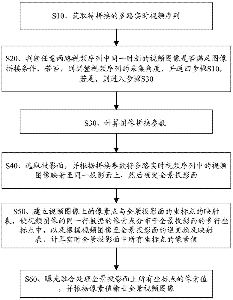
[0065] Step 2) Determine whether the video images in any two video sequences meet the image stitching conditions, if not, adjust the acquisition angle of the video sequence, and return to step 1); if so, calculate the image stitching parameters. The image stitching conditions include image integrity and overlapping regions of adjacent images; the image stitching parameters include focal length and rotation matrix.

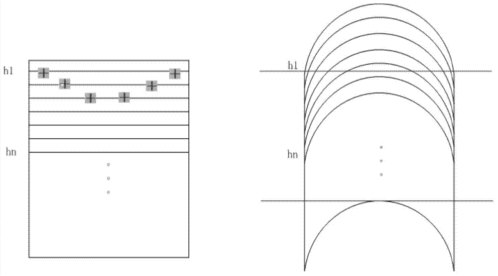
[0066] Step 3) Cylindrical projection transformation, obtaining the size of the panoramic projection surface and establishing a mapping table between the video image and the panoramic projection surface; and calculating the pixel value of each pixel on the panoramic canvas through projection inverse transformation; the cylindrical coordinates The transformation formula is as follows, where the original plane imag...

Embodiment 2

[0073] refer to Figure 7 , read video sequences sequentially from the multi-lens panoramic stitching camera, and the lenses are placed horizontally and vertically;

[0074] Step 1) Read in the video sequence from the multi-lens panoramic stitching camera in sequence, and place the lenses horizontally or vertically;

[0075] Step 2) Determine whether the video images in any two video sequences meet the image stitching conditions, if not, adjust the acquisition angle of the video sequence, and return to step 1); if so, calculate the image stitching parameters. The image stitching conditions include image integrity and overlapping regions of adjacent images; the image stitching parameters include focal length and rotation matrix.

[0076] Step 3) Spherical projection transformation, obtain the size of the panoramic projection surface and establish a mapping table between the video image and the panoramic projection surface; and calculate the pixel value of each pixel on the pan...


PUM


Abstract

The invention discloses a splicing device for a real-time high speed high definition panoramic video and a method thereof. The method comprises the steps: S10, obtaining spliced multipath real-time video sequences; S20, judging whether video images at the same moment in any two paths of video sequences meet the image splicing condition; S30, calculating an image splicing parameter; S40, selecting a projection face and mapping the video images in the multipath real-time video sequences to the same mapping face according to the splicing parameter, then determining the panoramic projection face; S50, establishing a mapping table of pixel points on the video images and coordinate points of the overall projection face; S60, conducting exposure and fusion processing on pixel values of all the coordinate points on the panoramic projection face and outputting the panoramic video images according to the pixel values. The splicing device for the real-time high speed high definition panoramic video and the method of the splicing device can greatly improve splicing efficiency of the images, ensure output quality of the images, and meet the requirement for real-time high speed high definition panoramic video.

Description

technical field [0001] The invention relates to the technical field of image processing, in particular to a real-time high-speed high-definition panoramic video splicing device and a method thereof. Background technique [0002] With the rapid development of monitoring systems today, the emergence of high-definition cameras allows people to see more clearly and obtain more details. However, people have put forward another requirement, that is, they can see more in the same scene. thing. The original method is to solve it by covering an area with several cameras, or using a fast dome to cruise and scan back and forth. But in some occasions, these methods can not fully meet the user's requirements, such as the need to determine the movement of people in the same screen, or need to use the things monitored in the same scene to explain some problems, this time you need panorama camera. The panoramic camera hardware in the prior art is divided into five modules: a video acquis...

Claims


Application Information

Patent Timeline
Patent Type & Authority Applications(China)
IPC IPC(8): H04N5/262
Inventor 彭俊林小晖吴雪梅阎妍
Owner SHENZHEN INFINOVA
Learn More