Device for automatic injection of drug doses

A technology of injection equipment and drugs, which is applied in the direction of automatic injectors, drug devices, syringes, etc., and can solve problems such as manual administration

Active Publication Date: 2014-04-30
梅纳里尼国际业务卢森堡股份有限公司
View PDF7 Cites 14 Cited by
  • Summary
  • Abstract
  • Description
  • Claims
  • Application Information

AI Technical Summary

Problems solved by technology

This type of auto-injector is commercially available under the trademark Twinject™ and allows the first dose to be administered automatically but the second dose must be administered manually

Method used


Image

  • Device for automatic injection of drug doses
  • Device for automatic injection of drug doses
  • Device for automatic injection of drug doses

Examples


Embodiment Construction

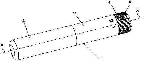
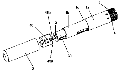
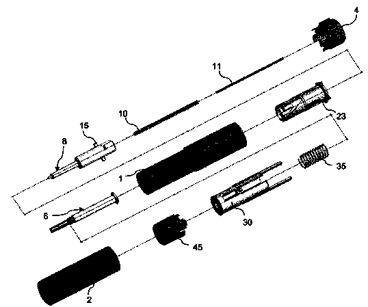
[0070] refer to Figure 1 to Figure 5 , the autoinjector device of the present invention comprises: a tubular outer body 1 (in particular a cylinder), which extends along the axis X and contains most of the device components. The outer body is formed by two coaxially aligned body parts 1a, 1b having different diameters and separated by a step 1c. The end of the removable end cap 2 abuts against the step 1c, said cap 2 covering the front end 3 of the device. As explained later, the vicinity of the other end (rear end) of the device is formed or marked with angularly spaced reference marks, such as the numerals 0, 1, 2, to denote the resting or storage state (0) of the device and the two operating state (1, 2). In this specification, the terms "front", "rear" and equivalents refer to parts of the device for needle exit, respectively axially opposite parts. It should also be noted that throughout this specification reference is always made to a device for the automatic injecti...


PUM


Abstract

A device for the automatic injection of doses of a drug compound comprising a sliding sheath (30) which, when depressed with its front end (3) against the injection site, interacts with cam means (26, 27, 28) to activate the triggering of a plunger (8), controlling the delivery of a drug dose. Plunger guide means (44) are provide for controlling the triggering sequence and means (4) for arming the device in the dose delivery condition. Automatic needle re-sheathing and resetting of a lock-out condition after each dose is delivered are provided. The number of the device components is reduced resulting in a simpler structure and cost reduction.

Description

technical field [0001] The present invention relates generally to a device for the injection of medicines, more precisely to an automatic injection of medicines, in particular for allergic emergencies, such as epinephrine, according to the required chronological order device of. In particular, the invention relates to a device for two consecutive automatic injections of two doses of a medicament. Background technique [0002] A number of devices of the above-mentioned type are known which allow a patient to self-administer one or more (typically two) doses of a drug. US patent 6575939 discloses an autoinjector device comprising a syringe housed within a housing formed by an inner part and an outer part which can slide relative to each other. By pressing the end of the inner part (needle exit end) against the patient's skin at the injection site, the outer part slides forward along the inner part, thereby unlocking the button. By pressing a button, the syringe and associat...

Claims


Application Information

Patent Timeline
Patent Type & Authority Applications(China)
IPC IPC(8): A61M5/20A61M5/315A61M5/32A61M5/00A61M5/31
CPCA61M5/3287A61M2205/582A61M5/3204A61M5/31553A61M5/3156A61M5/31535A61M5/20A61M2005/206A61M5/3232A61M2005/2013A61M2205/581A61M2005/3247
Inventor 马克·杰弗里·爱德豪斯菲利普·杰罗姆·德赖弗盖伊·康文·朱利安·摩斯利斯科特·亚历山大·路易斯
Owner 梅纳里尼国际业务卢森堡股份有限公司
Why Eureka
Try Eureka