Roller mill

A roller mill and grinding machine technology, applied in the field of roller mills, can solve the problems of expensive, unsuitable for complete, uniform and continuous material transportation, unable to guarantee the supply of raw materials, etc., and achieve the effect of energy saving and reliable continuous material transportation

Inactive Publication Date: 2014-04-30
LOESCHE GMBH
View PDF16 Cites 11 Cited by
  • Summary
  • Abstract
  • Description
  • Claims
  • Application Information

AI Technical Summary

Problems solved by technology

[0013] Due to its construction, a screw conveyor fitted to one side of the mill housing cannot in any case guarantee an undisturbed supply of raw material
Additional components in the wall of the abrasive cone are relatively expensive and in no way suitable for ensuring a complete, uniform and continuous material delivery

Method used


Image

  • Roller mill

Examples


Embodiment Construction

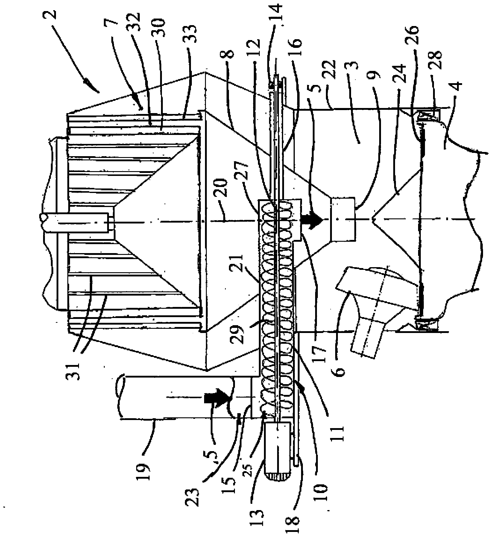
[0034] The roller mill 2 comprises a grinding disc 4 which rotates about a longitudinal axis 20 . The grinding disc 4 is provided with a grinding track 26 on which a grinding bed is formed from the raw material to be ground (not shown). Grinding rollers 6 arranged in fixed form and force-impacted form roll on this grinding bed with the assistance of a (not shown) suspension system and grind the raw material 5 conveyed with the assistance of a conveying system.

[0035] Only one grinding roller 6 is shown schematically in the figures. In principle, two, three, four or more grinding rollers can be arranged.

[0036] The ground abrasive material (not shown) is conveyed to the classifier 7 for classification in an updraft (not shown) which is conveyed to the Grinding chamber 3 , classifier 7 is arranged above grinding chamber 3 and is integrated into roller mill 2 in this exemplary embodiment.

[0037] The classifier 7 is provided with a rotor 30 which rotates about the longitu...


PUM


Abstract

The invention relates to a roller mill, in particular a coal mill, having a feed system which has an integrated screw feeder. The screw feeder is arranged virtually horizontally in the region of a grit cone and has a worm shaft which is guided through the roller mill and along the longitudinal axis thereof, both end sides of which are arranged in each case outside the roller mill and which is mounted at one end by way of a drive device and at the other end in a mounting outside the roller mill. The feed material is supplied to the screw conveyor outside the roller mill and is forcibly conveyed therein up to a trough-side ejection opening above a cone opening in the grit cone, and drops centrally onto the grinding bowl together with coarse grain rejected in the classifier. A uniform distribution of the feed material and improved running smoothness of the roller mill and a saving of energy are achieved, and soiling of the worm shaft is prevented.

Description

technical field [0001] The invention relates to a roller mill according to the preamble of claim 1 . [0002] The invention is particularly suitable for setting up roller mills for grinding raw coal. Background technique [0003] Roller mills comprise grinding discs or grinding plates with grinding tracks and elastically impinging grinding rollers, which roll on the grinding tracks or on the grinding bed formed there from the supplied raw material , such roller mills are used to grind a variety of materials (DE10224009B4, DE3100341A1 and DE3134601C2). [0004] The raw material to be ground in the grinding gap between the grinding roller and the grinding track can be conveyed laterally or centrally into the grinding chamber and the rotating grinding disc. [0005] In the case of an air-swept roller mill, the ground grinding material is conveyed into a rising air flow, for example an air flow, which enters the grinding chamber through a set of blades arranged in a ring aroun...

Claims


Application Information

Patent Timeline
Patent Type & Authority Applications(China)
IPC IPC(8): B02C15/00B02C15/04B02C23/02
CPCB02C15/04B02C23/30B02C23/02B02C15/007B02C23/24B02C23/32B02C2015/002B02C15/00
Inventor 迈克尔·克思奈
Owner LOESCHE GMBH
Why Eureka
Try Eureka