
Handle device

A technology for handles and conversion devices, which is applied in the direction of portable motorized devices, portable impact tools, electrical components, etc., can solve problems such as side effects and achieve low-cost effects

Active Publication Date: 2014-04-30
ROBERT BOSCH GMBH
View PDF8 Cites 0 Cited by
  • Summary
  • Abstract
  • Description
  • Claims
  • Application Information

AI Technical Summary

Problems solved by technology

[0004] Due to the required rigidity, an anti-vibration handle with an elastic connection on the hammer also induces a relative movement between hammer and handle as a side effect

Method used


Image

  • Handle device
  • Handle device
  • Handle device

Examples


Embodiment Construction

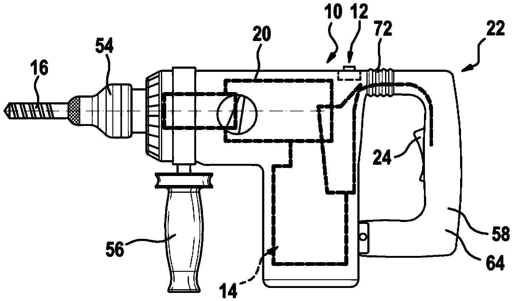
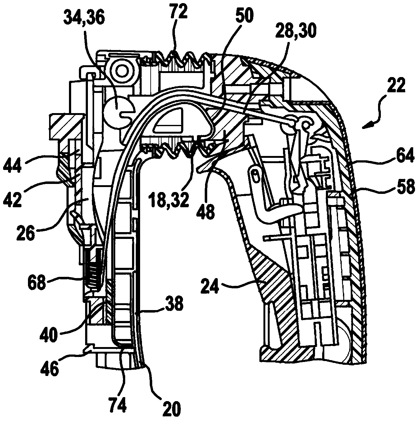
[0049]1 shows a schematic view of a hammer drill and / or chisel hammer as an example of a hand-held power tool 10 with a machine housing 20 , a tool holder movably arranged on the machine housing 20 The device 54 serves to exchangeably receive the plug-in tool 16 and the drive device 14 , which is accommodated in the machine housing 20 and has a drive unit and a transmission unit, for driving the plug-in tool 16 in different operating modes. In this case, the tool holder 54 is preferably arranged rotatably on the front side of the machine housing 20 . Furthermore, in the example according to FIG. 1 , a handle arrangement is provided on the side of the machine housing 20 opposite the end side of the machine housing 20 . In the present example, the handle arrangement includes a switch operator 24 for putting the drill hammer and / or chisel hammer into operation. The switch actuator 24 can be switched between two switching positions both monostable and bistable. Furthermore, an a...


PUM


Abstract

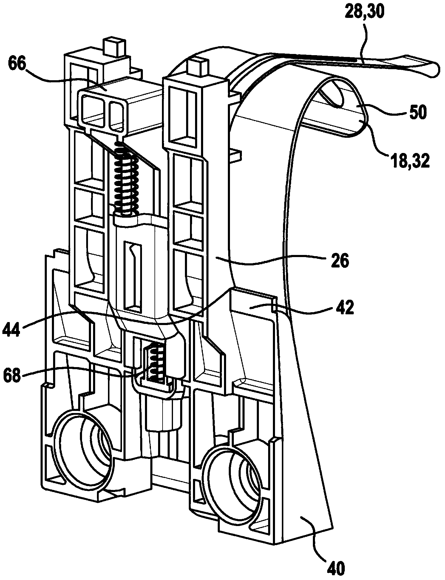
The invention relates to a handle device for a hand-held power tool, which hand-held power tool has an operating-mode switching device and a driving device for driving an insert tool in different operating modes, the handle device comprising at least one spring element (18) and a handle unit (22) attached in at least limitedly movable manner to a power tool housing (20). The handle element is at least partially vibrationally decoupled from the power tool housing (20) by means of the at least one spring element (18) and has a switch actuator (24) for starting up the driving device (14), wherein the switch actuator (24) can be switched between two switching positions in both a monostable manner and a bistable manner. According to the invention, the handle device has an intermediate plate (26), which is provided in the power tool housing (20) and which at least accommodates the spring element (18) at one end, and a control element (28), by means of which the switch actuator (24) interacts with the operating-mode switching device (12) in such a way that bistable switching is not possible in certain operating modes of the switch actuator (24).

Description

Background technique [0001] The invention relates to a handle arrangement for a hand-held power tool of the type according to the independent claims. [0002] The implementation of legal requirements, which include the limitation of vibration conditions on hand-guided power tools, has an ever-increasing significance in the field of this subject. Precisely in heavy hammer drills and / or chisel hammers, vibrations are very noticeable due to the high individual impact strength. Currently, legislation stipulates how long a user can continue to work with said machine, depending on the vibration level of the machine. If the load exceeds the limit value determined by the vibration, the permissible hours of use per day are reduced accordingly. [0003] Therefore, in product development, measures to reduce vibration are increasingly taken. The overarching goal is to further increase handling comfort and maintain the associated, realistic daily hours of use. In order to reduce vibrat...

Claims


Application Information

Patent Timeline
Patent Type & Authority Applications(China)
IPC IPC(8): B25D16/00B25D17/04B25D17/00B25F5/00H01H9/06
CPCB25D2250/381B25D17/00B25D17/043B25D2250/275B25D2250/371B25D2250/261B25D2250/265B25D2222/69B25F5/02B25D2222/57
Inventor P·海嫩C·迪姆A·屈恩勒W·布劳恩
Owner ROBERT BOSCH GMBH
Learn More