Self-floating type clamp iron for limiting core assembly pouring device

A self-floating, core-forming technology, applied in cores, mold boxes, casting and molding equipment, etc., can solve problems such as affecting production efficiency, many consumables, and tedious operations, so as to speed up production beats, reduce operating procedures, and avoid swelling. box effect

Active Publication Date: 2014-05-07
SUZHOU MINGZHI TECH
View PDF9 Cites 19 Cited by
  • Summary
  • Abstract
  • Description
  • Claims
  • Application Information

AI Technical Summary

Problems solved by technology

[0003] The traditional method is to first clamp the side of the sand mold with a C-shaped clamping block (or use a sand box to put the core group in), then place the weight on it, and then pour it. After the casting is solidified, remove the weight And the C-type clamping block (or sand box), the existing technical methods divide the measures to prevent the expansion into two processes (pressing the top, clamping the side), so it is more cumbersome to operate, especially when the side The clamping process (adding C-shaped clamping blocks or using a sand box) is much more complicated than the above pressing process (releasing the pressure iron), and it is very inconvenient whether it is clamping preparation before pouring or disassembly after pouring. Affect production efficiency
[0004] Chinese invention patent CN2336895Y discloses a clamping device for sand mold pressing iron used in an out-of-box molding production line for producing castings. The left and right splints are respectively connected to one end of the left and right connecting rod clamping mechanisms, and the other ends of the left and right connecting rod clamping mechanisms are connected to the active rod, which is a beam. However, this invention has a complicated structure and many consumables, and when realizing side-type clamping, it must rely on external force to realize the pressing of the active rod on the weight iron, which is not simple enough.
[0005] Chinese invention patent CN 1015782B discloses a device for providing weight and lateral support for boxless sand mold parts with a horizontal parting line during pouring, solidification and cooling. The device includes a weight and a splint, and the bottom surface of the lower mold is placed On a conveyor, the device also includes generally "L" shaped arms, the two "L" shaped arms are mounted opposite each other in the same vertical plane passing through the sand mold part and in a horizontal plane They are placed laterally staggered from each other, and are rotatably connected to the weight iron at the position. Although this invention can better realize the upper mold pressing and side mold clamping of the sand mold at the same time, the splint needs an attached fixing structure to be clamped to the sand mold. In terms of side shape, the structure and production process are relatively complicated

Method used


Image

  • Self-floating type clamp iron for limiting core assembly pouring device
  • Self-floating type clamp iron for limiting core assembly pouring device
  • Self-floating type clamp iron for limiting core assembly pouring device

Examples


Embodiment 1

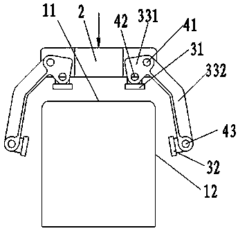
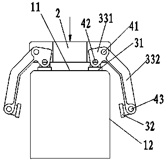
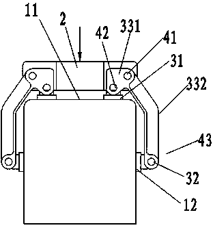
[0019] Embodiment one: see Figure 1-Figure 5 , as shown in the legend therein, a self-floating weight used for the limit core group pouring device is used to simultaneously compress the upper mold 11 of the core group and the side mold 12 of the clamped core group, including a weight Body 2 and a self-floating clamping mechanism, which includes four clamping devices symmetrically arranged front, rear, left and right, each clamping device includes an upper pressing block 31, a side pressing block 32 and a clamping lever, the clamping lever is hingedly connected to the weight body 2 through the first rotating shaft 41 and rotates in the vertical plane with the first rotating shaft 41 as a fulcrum, and one end of the clamping lever extends to the weighting body 2 The bottom of the clamping lever (between the weight body 2 and the upper type 11) forms the first lever arm 331, and the other end of the clamping lever extends to the bottom of the first lever arm 331 (outside the sid...

Embodiment 2

[0023] Embodiment 2: The rest is the same as that of Embodiment 1, the difference is that an easy-to-rotate bearing is provided between the above-mentioned clamping lever and the first rotating shaft, and a bearing is also provided between the above-mentioned first lever arm and the second rotating shaft. With the bearing that is easy to rotate, the above-mentioned second lever arm is directly fixedly connected with the side pressure block, and the adjustment of the side pressure block cannot be realized without being connected through the above-mentioned third rotating shaft.

Embodiment 3

[0024] Embodiment 3: The rest is the same as that of Embodiment 1, the difference is that the above-mentioned clamping lever can use one or more combinations of connecting rod structure or wedging structure to realize the self-weight of the weight body It is converted into side clamping force, which is a prior art, and will not be described in detail here.


PUM


Abstract

The invention discloses self-floating type clamp iron for limiting a core assembly pouring device. The self-floating type clamp iron comprises a clamp iron body and further comprises a self-floating type clamping mechanism, wherein the self-floating type clamping mechanism comprises clamping devices which are symmetrically arranged in a front-back manner and in a left-right manner; each clamping device comprises an upper pressing block, a side pressing block and a linkage structure; each linkage structure is movably connected with the clamp iron body; each upper pressing block is connected with the corresponding linkage structure, applies vertical acting force along the vertical direction and bears vertical reverse acting force under self-gravity acting force of the clamp iron body; each side pressing block is connected with the corresponding linkage structure, applies horizontal acting force along the horizontal direction and bears horizontal reverse acting force under vertical reverse acting force; a side mould of a core assembly is automatically clamped when an upper mould of the core assembly is compacted so as to realize the limitation of the core assembly pouring device (the core assembly), operation procedures are reduced and the production takt is accelerated.

Description

technical field [0001] The invention relates to a self-floating weight, in particular to a self-floating weight used for a limiting core casting device. Background technique [0002] When pouring the core group, in addition to the upper mold of the core group will be lifted up by the molten metal, the side mold of the core group will also be expanded by the molten metal, so before pouring, do It is best to prevent the upper model from lifting and the preventive measures from the side model. [0003] The traditional method is to first clamp the side of the sand mold with a C-shaped clamping block (or use a sand box to put the core group in), then place the weight on it, and then pour it. After the casting is solidified, remove the weight And the C-type clamping block (or sand box), the existing technical methods divide the measures to prevent the expansion into two processes (pressing the top, clamping the side), so it is more cumbersome to operate, especially when the side ...

Claims


Application Information

Patent Timeline
Patent Type & Authority Applications(China)
IPC IPC(8): B22C21/08B22C9/10
Inventor 杨林龙程建荣夏志远毛俊璋徐渭江
Owner SUZHOU MINGZHI TECH
Why Eureka
Try Eureka