Feeding device for heat treatment of steel balls

A material distributing device and steel ball technology, applied in the direction of transportation and packaging, conveyor objects, etc., can solve the problems of large safety hazards, messy cloth, and ejected steel balls, etc., to achieve huge economic benefits, simple structure, and accurate cloth Effect

Inactive Publication Date: 2014-05-07
湖北中冶窑炉有限公司
View PDF0 Cites 4 Cited by
  • Summary
  • Abstract
  • Description
  • Claims
  • Application Information

AI Technical Summary

Problems solved by technology

[0003] The purpose of the present invention is to solve the problem that the traditional steel ball heat treatment distributing device is easy to cause the steel ball to be unable to push or the steel ball is ejected, which has great safety hazards, and the steel ball is easy to fall when the steel ball is dumped from the V-shaped collecting tank to the V-shaped feeding tank. Rolling to the outside of the V-shaped feeding trough, the cloth is messy, prone to jamming, kiln shutdown and high equipment failure rate, etc., providing a distribution device for steel ball heat treatment

Method used


Image

  • Feeding device for heat treatment of steel balls
  • Feeding device for heat treatment of steel balls
  • Feeding device for heat treatment of steel balls

Examples


Embodiment Construction

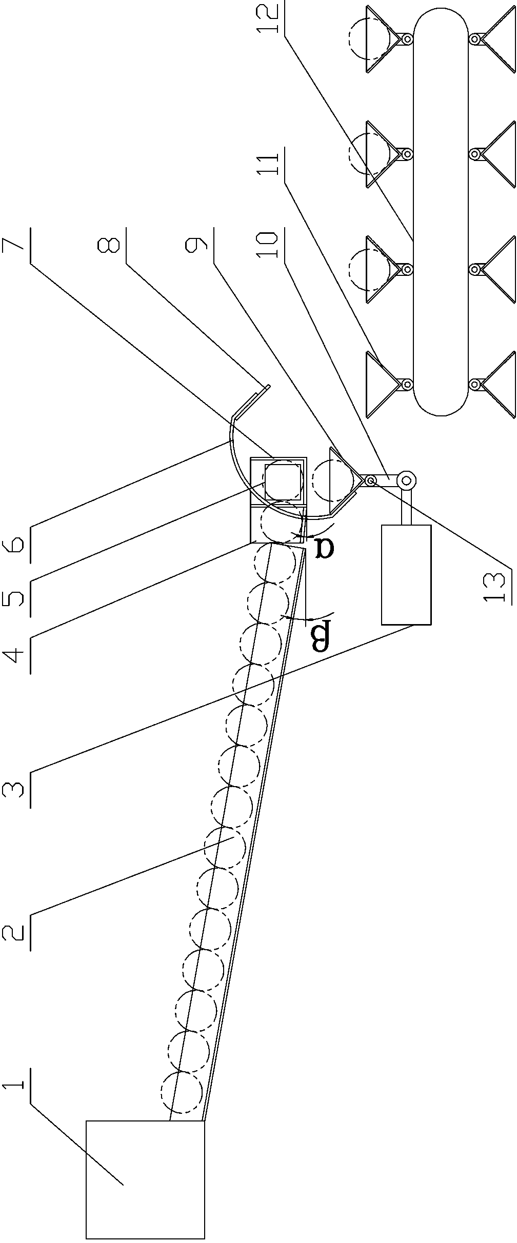
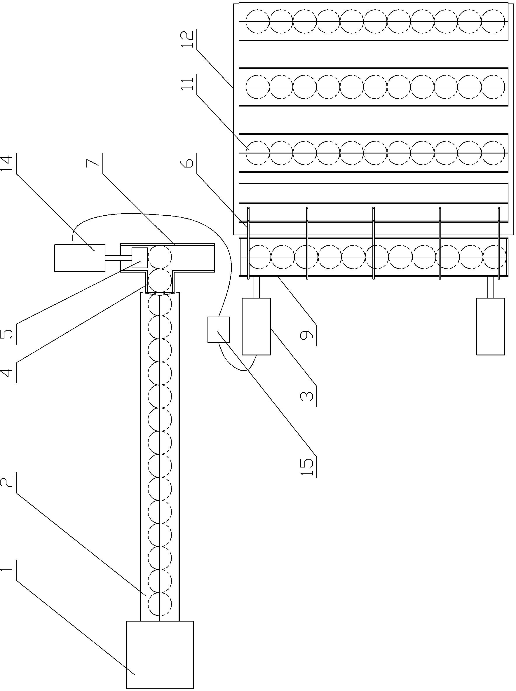
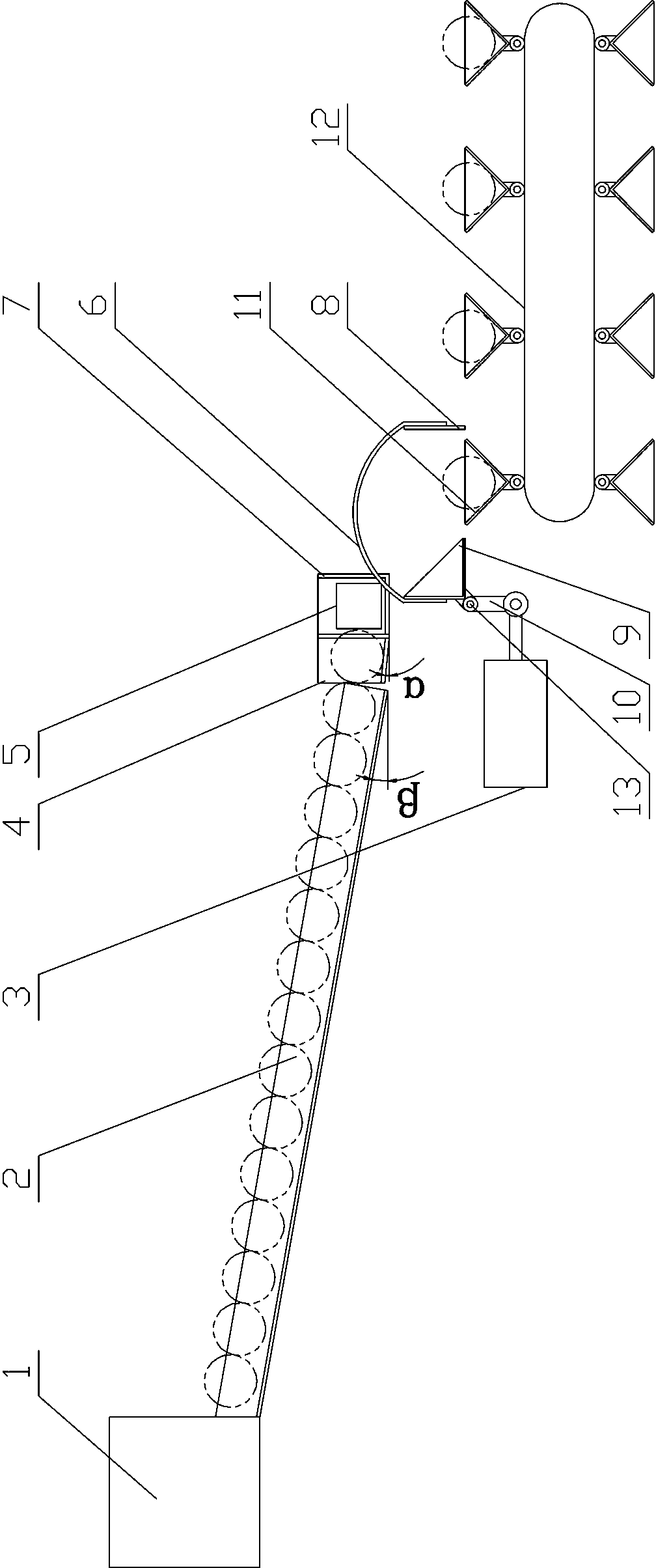
[0015] see figure 1 and figure 2 , the present invention has a collection box 1, the side of the collection box 1 is equipped with a V-shaped feeding track 2 arranged obliquely downward, and a horizontally arranged pusher groove 7 is connected to the end of the V-shaped feeder track 2, and the pusher groove 7 is connected to the The V-shaped feeding track 2 is vertically arranged, and the left side of the pushing groove 7 (the left side of the pushing groove 7 corresponds to figure 2 The front side of the middle pusher tank 7) is provided with a pusher cylinder 14 with a counter, and the end of the piston head of the pusher cylinder 14 is connected with a pusher head 5, which is located in the pusher tank 7, and the pusher tank 7 Right side (the right side of the pushing groove 7 corresponds to figure 2 The rear side of the middle pushing trough 7) is provided with a V-shaped collecting trough 9, and the V-shaped collecting trough 9 and the pushing trough 7 are arranged a...


PUM


Abstract

A feeding device for heat treatment of steel balls comprises an aggregating box, a V-shaped feeding rail and a pushing groove; the V-shaped feeding rail is arranged on one side of the aggregating box; the pushing groove is in abutting connection with the V-shaped feeding rail; the left side of the pushing groove is provided with a pushing cylinder; a V-shaped aggregating groove with a rotating shaft is formed under the right side of the pushing groove; a connecting rod is arranged under the rotating shaft; a piston head and a reversing cylinder are arranged under the V-shaped aggregating groove; the reversing cylinder is hinged to the connecting rod; a controller is connected between the reversing cylinder and the pushing cylinder; a conveyor belt with a V-shaped feeding groove is arranged under the front side of the V-shaped aggregating groove; the bottom of the V-shaped aggregating groove is level with the top of the V-shaped feeding groove which is formed above the conveyor belt. The feeding device is characterized in that a steel ball buffer groove is added between the pushing groove and the tail end of the V-shaped feeding rail; the V-shaped aggregating groove is connected with a stopping plate through arc-shaped connecting ribs; the end portion of the stopping plate is located on the outer side of the V-shaped feeding groove which is formed above the conveyor belt and is closest to the V-shaped aggregating groove when the V-shaped aggregating groove turns over to the limit position. According to the feeding device for the heat treatment of the steel balls, the steel balls can be smoothly pushed out and accurately arranged in the V-shaped feeding groove, the failure rate is low, and the use is safe and reliable.

Description

technical field [0001] The invention relates to an automatic mechanical distributing device, in particular to a distributing device for heat treatment of steel balls. Background technique [0002] At present, the traditional material distributing device for steel ball heat treatment has a collection box, one side of the collection box is equipped with a V-shaped feeding track arranged obliquely downward, and a horizontally arranged pushing groove is connected to the end of the V-shaped feeding track. The groove and the V-shaped feeding track are vertically arranged. There is a pushing cylinder with a counter on the left side of the pushing groove. The piston head end of the pushing cylinder is connected with a pushing head, which is located in the pushing groove. There is a V-shaped collecting trough at the bottom of the side, the V-shaped collecting trough and the pushing trough are arranged at intervals, and the horizontal distance between the two troughs is smaller than t...

Claims


Application Information

Patent Timeline
Patent Type & Authority Applications(China)
IPC IPC(8): B65G47/06
Inventor 樊利军刘聪何伟
Owner 湖北中冶窑炉有限公司
Why Eureka
Try Eureka