Optical fiber wringing equipment

A kind of equipment and optical fiber technology, which is applied in the field of optical fiber twisting equipment, can solve the problems of aggravating optical fiber damage, delamination, difficulty in meeting the demand of optical fiber production speed, delamination of optical fiber damage, etc., and achieve the effect of reducing adverse effects

Inactive Publication Date: 2014-05-07
FUTONG GROUP CO LTD
View PDF7 Cites 8 Cited by
  • Summary
  • Abstract
  • Description
  • Claims
  • Application Information

AI Technical Summary

Problems solved by technology

[0005] However, since the optical fiber will be rubbed and squeezed by the two twisting wheels during the twisting process, it is easy to cause damage, delamination and other adverse effects on the optical fiber
[0006] Secondly, when using the above-mentioned equipment to twist the optical fiber, if the

Method used


Image

  • Optical fiber wringing equipment
  • Optical fiber wringing equipment
  • Optical fiber wringing equipment

Examples


Embodiment Construction

[0039] The embodiment of the invention discloses an optical fiber twisting device, so as to reduce the adverse effect of the device on the optical fiber and increase the production speed of the optical fiber under the premise of ensuring the PMD of the optical fiber.

[0040] The following will clearly and completely describe the technical solutions in the embodiments of the present invention with reference to the accompanying drawings in the embodiments of the present invention. Obviously, the described embodiments are only some, not all, embodiments of the present invention. Based on the embodiments of the present invention, all other embodiments obtained by persons of ordinary skill in the art without making creative efforts belong to the protection scope of the present invention.

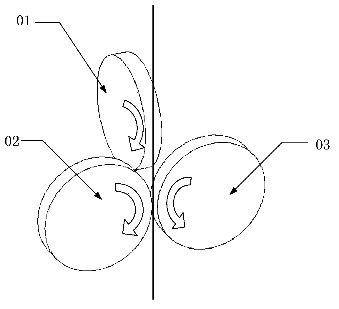
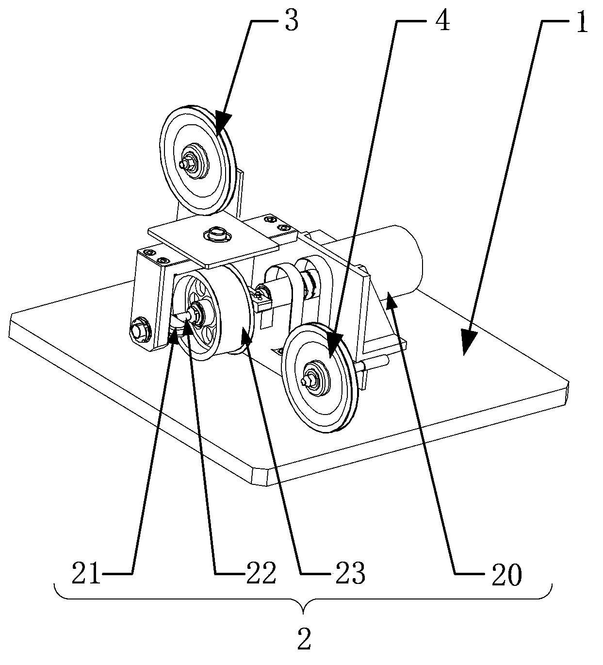
[0041] Please refer to figure 2 , In the optical fiber twisting equipment provided by the present invention, it includes a frame 1, a swing wheel device 2, a front anti-vibration wheel 3 and a ...


PUM


Abstract

The invention discloses optical fiber wringing equipment. The equipment comprises a frame, a swing wheel device fixedly arranged on the frame, a front vibration-stopping wheel, and a rear vibration-stopping wheel, wherein the front vibration-stopping wheel and the rear vibration-stopping wheel are rotatingly arranged on the frame, and the rotation axes of the front vibration-stopping wheel and the rear vibration-stopping wheel are in a parallel relationship; the swing wheel device comprises a Z-shaped component, which is driven to rotate by a power device fixedly arranged on the frame; the Z-shaped component comprises two crank handles, wherein the rotation axes of the two crank handles are overlapped, one of the two crank handles is connected to the power device, a swing wheel shaft, whose two ends are respectively connected to the two crank handles, and a swing wheel fixedly arranged in the middle position of the swing wheel shaft; and the axis of the swing wheel shaft intersects with the rotation axis of the crank handles. When using the optical fiber wringing equipment, optical fibers carry out complete vibration between the front vibration-stopping wheel and the swing wheel, and between the swing wheel and the rear vibration-stopping wheel; thus the vibration buffering zone of optical fibers is increased, the wringing force on optical fibers is more even, the non-roundness degree of optical fiber is optimized, the reject rate caused by layering and damage of optical fibers is largely reduced, PMD of optical fibers is reduced, and the actual production speed of optical fibers is improved at the same time.

Description

technical field [0001] The invention relates to the technical field of optical fiber production, and more specifically, relates to an optical fiber twisting device. Background technique [0002] In recent years, the telecommunications market has developed rapidly, and the number of residential users and business users has increased significantly, which has also promoted the construction of optical fiber networks. [0003] Optical fiber communication systems are developing toward large capacity, high speed, and long distances, making optical fiber performance defects such as polarization mode dispersion (Polarization Mode Dispersion, abbreviated as: PMD), which were originally negligible for low-speed systems, become the main reason for limiting transmission distances. factor. The internal factors that cause the PMD instability of the single-mode fiber include the non-circularity of the fiber core and the consistency of the expansion coefficient of the fiber material. [00...

Claims


Application Information

Patent Timeline
IPC IPC(8): C03B37/10
Inventor 赵刚
Owner FUTONG GROUP CO LTD
Why Eureka
Try Eureka