
Fan blade balance correction method

A balancing and fan blade technology, which is applied to the components of pumping devices for elastic fluids, non-variable-capacity pumps, machines/engines, etc., can solve the problems of manpower and man-hours, poor balance effect, weight error, etc. , to achieve the effect of saving man-hours and achieving the best balance

Inactive Publication Date: 2014-05-07
ASIA VITAL COMPONENTS SHENZHEN CO LTD
View PDF6 Cites 3 Cited by
  • Summary
  • Abstract
  • Description
  • Claims
  • Application Information

AI Technical Summary

Problems solved by technology

[0004] Although using the above method can make the fan blades achieve the balance effect, but the steps of adding or reducing the balance soil to the blades need to be manually performed during the test, which causes labor and time-consuming and complicated procedures. The process of increasing or decreasing the balance soil is prone to weight errors, which leads to more manpower and time-consuming and poor balance effects during testing; therefore, conventional methods have the following disadvantages:
[0005] 1. Consuming manpower and working hours;
[0006] 2. The procedure is complicated;
[0007] 3. Prone to weight error;
[0008] 4. Poor balance effect

Method used


Image

  • Fan blade balance correction method
  • Fan blade balance correction method
  • Fan blade balance correction method

Examples


Embodiment Construction

[0038] The above-mentioned objects of the present invention and their structural and functional characteristics will be described with reference to the preferred embodiments of the accompanying drawings.

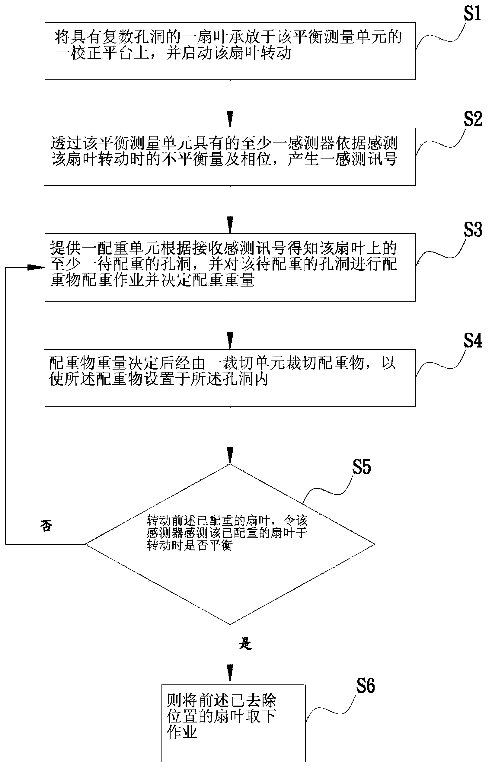
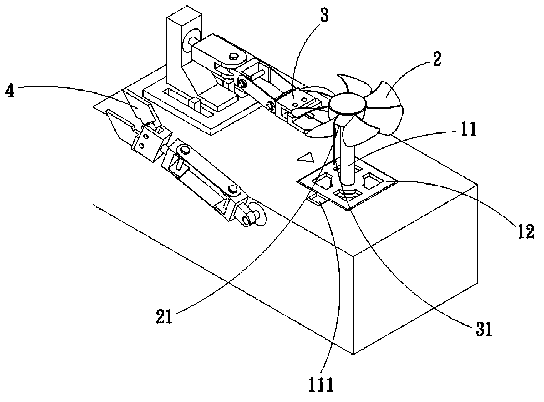
[0039] Please refer to Fig. 1 and Figs. 2A-2D, which are the flow chart and implementation diagram of the first embodiment of the fan blade balance adjustment method of the present invention. As shown in the figures, the fan blade balance adjustment method of the present invention It is applied to a balance adjustment device 1, the balance adjustment device 1 has a balance measurement unit 11, and the fan blade balance adjustment method includes the following steps:

[0040] (S1) a fan blade with a plurality of holes is supported on a calibration platform of the balance measurement unit, and the fan blade is started to rotate;

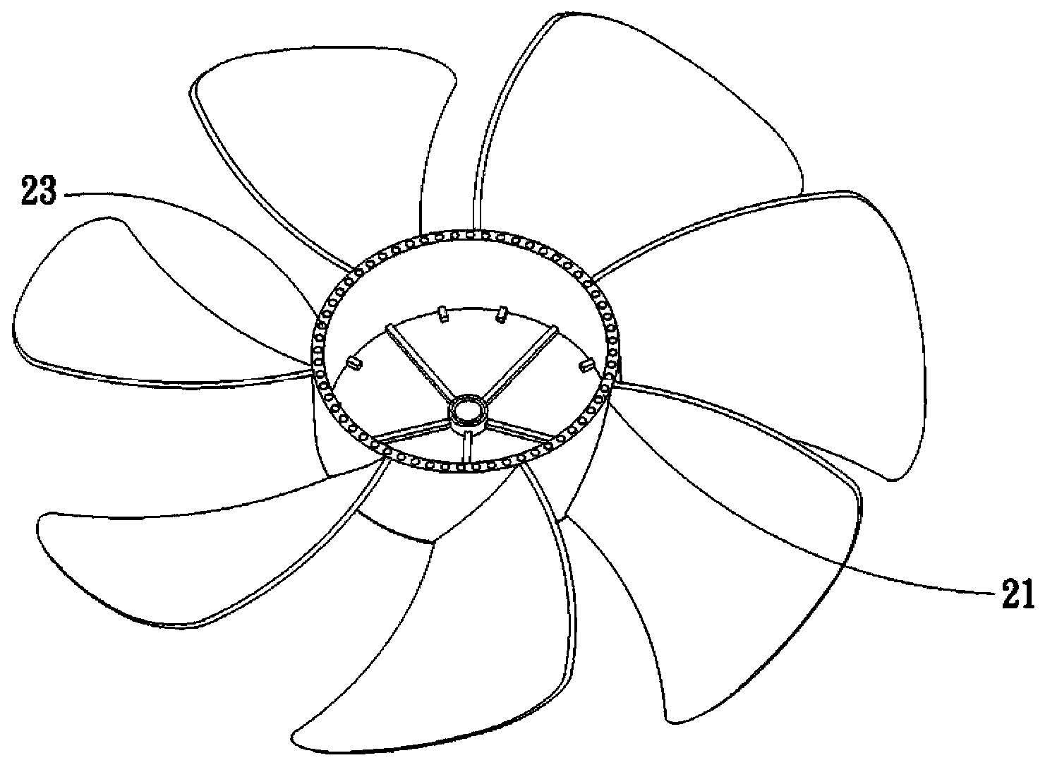
[0041] A fan blade 2 is provided, the bottom 21 of the fan blade 2 has a plurality of holes 23 in this embodiment, and the fan blade 2 is supported ...


PUM


Abstract

Disclosed is a fan blade balance correction method. A fan blade is disposed on a balance measuring unit and is started to rotate; a sensor of the balance measuring unit is used for sensing the unbalance amount of the fan blade during rotate and generating a sensing signal; a counter weight unit obtains at least one hole to be countered weighted according to the sensing signal and performs counter weight counter weighting on the at least one hole to be countered weighted. Accordingly, automatic measuring and counter weighting are achieved effectively, and work hours and manufacture costs are saved.

Description

technical field [0001] The present invention relates to a fan blade balance adjustment method, in particular to a fan blade balance adjustment method which can automatically adjust the fan blade balance and save man-hours and manufacturing costs. Background technique [0002] With the vigorous development of the high-tech industry, the functions of various electronic products have become more and more powerful, so that the electronic components built in the electronic products will generate a large amount of waste heat during operation. The heat dissipation area further improves the heat dissipation effect. However, the heat sink and the heat dissipation fins only dissipate heat by means of radiation, and the heat dissipation effect is limited. Therefore, an additional heat dissipation fan with improved heat dissipation efficiency must be added to dissipate the heat from the heat sink or the heat dissipation fins. In order to improve the heat dissipation performance, the coo...

Claims


Application Information

Patent Timeline
Patent Type & Authority Applications(China)
IPC IPC(8): F04D29/66
Inventor 蔡柏彬
Owner ASIA VITAL COMPONENTS SHENZHEN CO LTD
Learn More