Novel hydraulic lifting appliance

A technology of hydraulic lifting and hydraulic lifting rod, which is applied to mechanical equipment, lifting devices, fluid pressure actuating devices, etc., can solve the problems of poor stability, limited lifting weight, and inability to realize the first separation of the double nets, and achieve stable operation, The effect of automatically maintaining the desired height

Active Publication Date: 2014-05-07
YANTAI FUTURE AUTOMATIC EQUIP
View PDF5 Cites 11 Cited by
  • Summary
  • Abstract
  • Description
  • Claims
  • Application Information

AI Technical Summary

Problems solved by technology

In this case, the original mechanical and electric lifting equipment cannot meet the status quo, so the hydraulic lifting equipment applied to the double network has been developed accordingly.
The existing electric and mechanical lifting equipment cannot meet the following requirements:
[0003] 1. The existing lifting equipment can only load one kind of antenna and cannot be applied to dual-network emergency communication vehicles, and cannot realize the main function of separating the two networks first and merging them at the end when recycling
[0004] 2. The vol

Method used


Image

  • Novel hydraulic lifting appliance
  • Novel hydraulic lifting appliance
  • Novel hydraulic lifting appliance

Examples


Embodiment 1

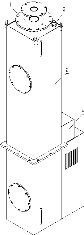
[0028] Embodiment 1: A kind of novel hydraulic lifting equipment (referring to figure 1 , see figure 2 , image 3 ,), which includes hydraulic lifting rod 1, hydraulic system 2, laser range finder 3, electric control box 4. The hydraulic system 2 is provided with a hydraulic lifting rod 1, and the hydraulic system 2 is provided with a laser rangefinder 3 and an electric control box 4.

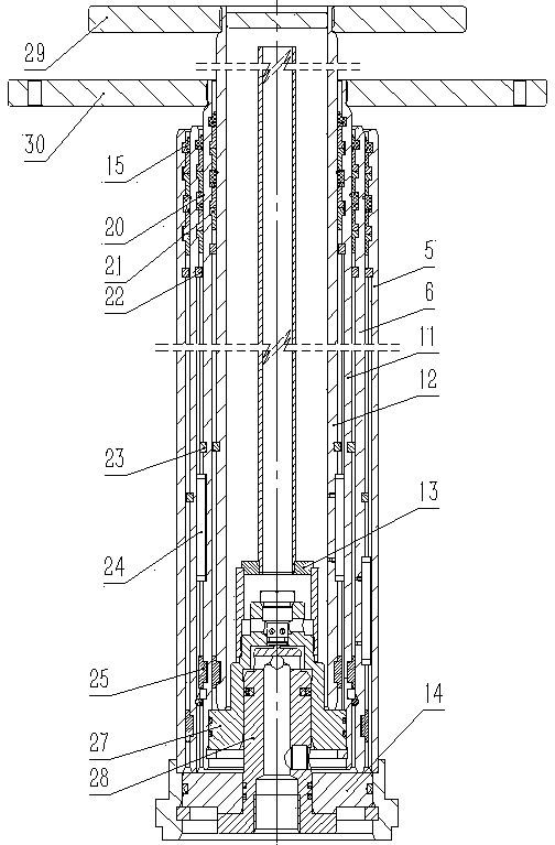
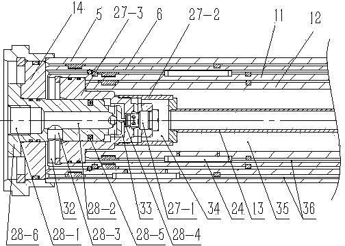
[0029]The present embodiment is three stages, which can rise 9 meters. The hydraulic lifting rod 1 includes a cylinder barrel 5, a primary piston rod 6 is arranged in the cylinder barrel 5, a secondary piston rod 11 is arranged in the primary piston rod 6, and a secondary piston rod 11 is arranged in the primary piston rod 6. 11 is provided with the innermost piston rod 12, the innermost piston rod 12 is provided with an exhaust pipe 13, a first-level sealing assembly 15 is arranged between the cylinder barrel 5 and the first-level piston rod 6, and the first-level piston rod 6 and A second...

Embodiment 2

[0037] Embodiment 2: A kind of novel hydraulic lifting equipment (see figure 1 , Figure 4 , Figure 5 ,) The hydraulic lifting rod in this embodiment has seven stages, which can rise 18 meters. Its structure and principle are basically the same as in Embodiment 1. 7. Three-stage piston rod 8, four-stage piston rod 9, five-stage piston rod 10, one-stage piston rod 6 is provided with two-stage piston rod 7, two-stage piston rod 7 is provided with three-stage piston rod 8, three-stage The piston rod 8 is provided with a four-stage piston rod 9, the four-stage piston rod 9 is provided with a five-stage piston rod 10, the five-stage piston rod 10 is provided with a secondary piston rod 11, a primary piston rod 6 and a secondary piston rod 7 is provided with a secondary seal assembly 16, between the secondary piston rod 7 and the tertiary piston rod 8 is provided with a tertiary seal assembly 17, between the tertiary piston rod 8 and the fourth piston rod 9 there are four A seco...


PUM


Abstract

The invention discloses a novel hydraulic lifting appliance. The novel hydraulic lifting appliance comprises a hydraulic lifting rod (1), a hydraulic system (2), an electric control box (4) and a laser range finder (3), wherein the hydraulic lifting rod (1) comprises a cylinder barrel (5), a primary piston rod (6), a secondary piston rod (11), an innermost-stage piston rod (12), an exhaust pipe (13), a sealing assembly, a support ring (25), a shaft limiting key (23), a hole limiting key (22), a long key groove (36) and a guide key (24); a one-way valve opening plunger assembly (28) is arranged in a rear cover (14), and comprises a plunger (28-6), an oil port (28-1), a channel (28-2), a reverse one-way valve (28-3) and a thimble; a one-way sealing assembly (27) is arranged in the secondary piston rod (11), and comprises a sealing plunger (27-3) and a one-way (27-1), and the sealing plunger (27-3) is connected to an exhaust pipe seat (27-2) connected with the exhaust pipe (13). The novel hydraulic lifting appliance is capable of preventing rotation in the total travel and provided with the laser range finder so that self-detection and self-control of the positions of the piston rods are realized, and moreover, the desired heights of the piston rods can be maintained automatically and the lifting order of the piston rods is controllable.

Description

Technical field: [0001] The invention relates to a hydraulic lifting device, in particular to a new type of hydraulic lifting device which is anti-rotation in full stroke and equipped with a laser range finder to realize autonomous detection and control of antenna rising height, automatic maintenance of required height and controllable lifting sequence . Background technique: [0002] With the rapid development of communication technology, 2G, 3G, and 4G networks have emerged and been widely used. At the same time, emergency communication equipment also needs to keep up with the development of communication technology. In this case, the original mechanical and electric lifting equipment cannot meet the status quo, so the hydraulic lifting equipment applied to the double network has been developed accordingly. The existing electric and mechanical lifting equipment cannot meet the following requirements: [0003] 1. The existing lifting equipment can only load one kind o...

Claims


Application Information

Patent Timeline
IPC IPC(8): F15B15/16F15B13/04F15B15/20F15B21/08B66F3/42B66F3/44
Inventor 孟令英徐鹏翔马龙鹏杨远义曹常贞王润香林志海
Owner YANTAI FUTURE AUTOMATIC EQUIP
Why Eureka
Try Eureka