Supercharge Your Innovation With Domain-Expert AI Agents!

Control valve

A control valve and valve body technology, applied in the direction of sliding valve, valve detail, valve device, etc., can solve the problems of large force required in an instant, easy to damage the sealing parts, valve stem and control parts of the control valve, etc., to reduce the difficulty, Instantaneous power is small, not easy to damage the effect

Active Publication Date: 2014-05-07
NINGBO TIANJILONG INTELLIGENT CONTROL TECH
View PDF4 Cites 10 Cited by
  • Summary
  • Abstract
  • Description
  • Claims
  • Application Information

AI Technical Summary

Problems solved by technology

[0002] The size of the control valve is increasing day by day, so when it is opened and closed, it requires a large force in an instant, and not only needs to be equipped with a larger power actuator, but also easily damages the sealing parts, valve stem and control parts of the control valve

Method used


Image

  • Control valve
  • Control valve
  • Control valve

Examples


Embodiment Construction

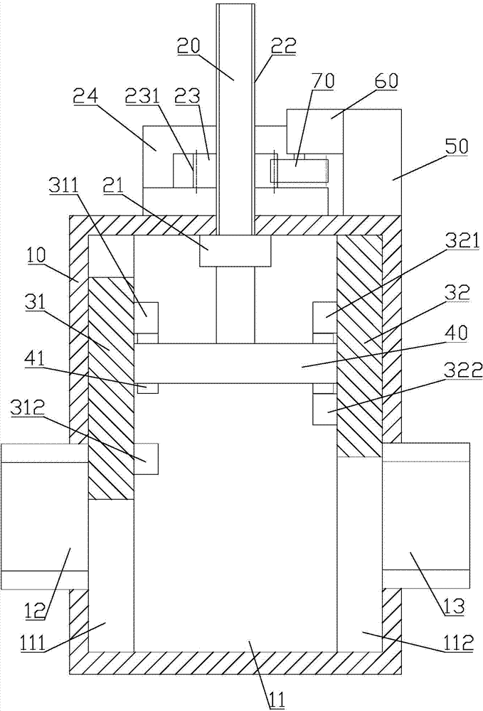
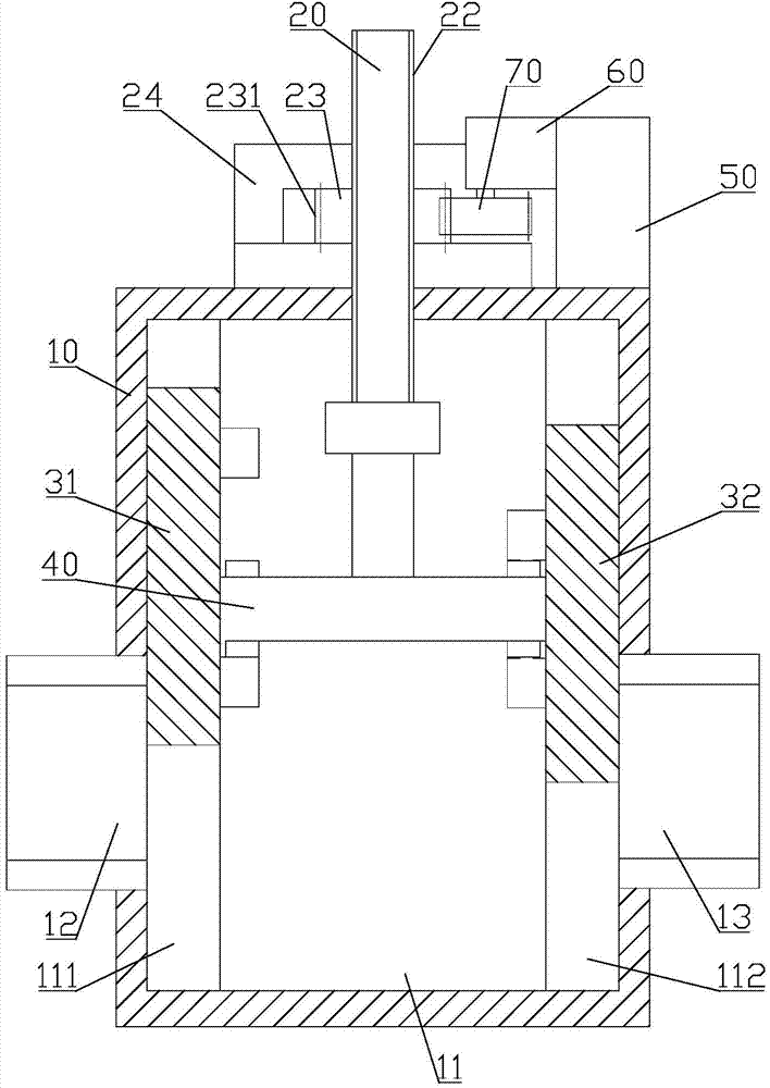
[0021] Examples, see Figure 1 to Figure 3 Shown: control valve, comprises valve body 10, and this valve body 10 has inner cavity 11, and the left side wall of this inner cavity 11 is provided with water outlet 12, and right side wall is provided with water inlet 13, and upper side wall is provided with There is a valve stem 20 .

[0022] Specifically, the inner cavity 11 is in the shape of a cuboid or a cube, and the left side of the inner cavity 11 is provided with a left chute 111 that goes up and down, and the right side of the cavity 11 is provided with a right chute 112 that goes up and down. A left sealing plate 31 is slidably disposed in the left chute 111 , and a right sealing plate 32 is slidably disposed in the right chute 112 . That is, both the left sealing plate 31 and the right sealing plate 32 can move up and down. The left side of the left sealing plate 31 matches the water outlet 12 , and the right side of the right sealing plate 32 matches the water inlet ...


PUM


Abstract

The invention discloses a control valve. When the control valve is opened and closed, a right sealing board always moves earlier than a left sealing board, so that opening and closing are conduced in a staged mode and the control valve saves labor. Meanwhile, after a servo motor drives a nut to rotate, the principle of a screw rod and nut mechanism is utilized to enable the left sealing board and the right sealing board to move, and the opening and closing difficulty is further reduced.

Description

technical field [0001] The invention relates to the technical field of control valves, in particular to a control valve. Background technique [0002] The size of the control valve is increasing day by day, so that when it is opened and closed, it requires a large force in an instant, and not only needs to be equipped with a larger power actuator, but also easily damages the sealing parts, valve stem and control parts of the control valve. Contents of the invention [0003] The object of the present invention is to provide a control valve which requires less instantaneous force for opening and closing and is not easily damaged. [0004] The technical solution adopted in the present invention is: the control valve includes a valve body, the valve body has an inner cavity, the left side wall of the inner cavity is provided with a water outlet, the right side wall is provided with a water inlet, and the upper side wall is provided with a water outlet. with stem, [0005] Th...

Claims


Application Information

Patent Timeline
IPC IPC(8): F16K3/02F16K3/30F16K31/53
CPCF16K3/029F16K3/314F16K31/047
Inventor 李洪峰易松达孙得浩王昌林
Owner NINGBO TIANJILONG INTELLIGENT CONTROL TECH
Features
  • R&D
  • Intellectual Property
  • Life Sciences
  • Materials
  • Tech Scout
  • Unparalleled Data Quality
  • Higher Quality Content
  • 60% Fewer Hallucinations
Learn More