Apparatus and method for detecting the radial runout of shaft component

A technology of shaft parts and radial runout, which is applied in measuring devices, mechanical measuring devices, and mechanical devices, etc., can solve the problems of detection environment, detection conditions, large detection workload, low efficiency, etc., and achieve reduction The effect of detecting workload, ensuring detection accuracy and improving detection efficiency

Inactive Publication Date: 2014-05-07
SHANGHAI BAOSTEEL IND TECHNOLOGICAL SERVICE
View PDF7 Cites 5 Cited by
  • Summary
  • Abstract
  • Description
  • Claims
  • Application Information

AI Technical Summary

Problems solved by technology

[0004] Using this method for radial runout detection, the shaft parts need to be placed on the machine tool or special rotating equipment, which is greatly affected by the detection environment and detection conditions. Especially for some large shaft parts, special machine tools need to be placed for rotation and detection. Heavy workload and low efficiency
[0005] The radial runout detection of shaft parts is a routine detection item in the metallurgical and manufacturing industries. Taking the radial runout detection of rolls in the metallurgical industry as an example, if the original detection method is used, since most production sites do not have the radial runout detection conditions, the rolls It is necessary to regularly or irregularly arrange inspections at the processing and manufacturing center, which will have a certain impact on the normal production order and increase the cost of equipment maintenance and repair

Method used


Image

  • Apparatus and method for detecting the radial runout of shaft component
  • Apparatus and method for detecting the radial runout of shaft component

Examples


Embodiment Construction

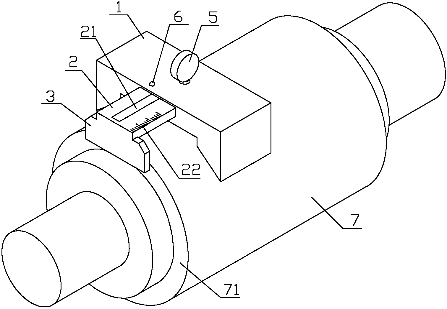
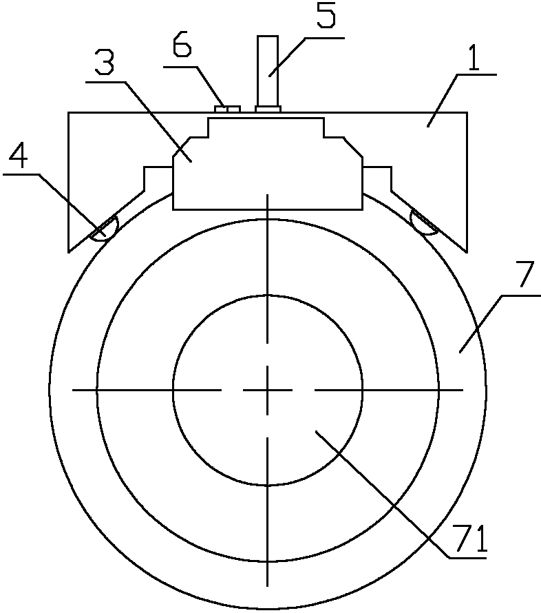
[0017] Such as figure 1 with figure 2 As shown, the radial runout detection device for shaft parts of the present invention includes a saddle 1, a dial indicator 5, a slide plate 2, a positioning plate 3, a fixing bolt 6 and two balls 4, and the center of the top surface of the saddle 1 is set There is a through hole and a screw hole is provided on one side of the through hole, a chute is provided in the horizontal direction on the top edge of the saddle seat 1, and the positioning plate 3 is vertically arranged at one end of the slide plate 2, and the slide plate 2 is provided with a long groove 21 and is located in the chute on the top edge of the saddle seat 1, the position of the through hole on the top surface of the saddle seat 1 matches the position of the long groove of the slide plate 2, and the fixing bolt 6 is screwed on the saddle In the screw hole on the top surface of the saddle 1 and against the slide plate 2, the dial indicator 5 is arranged on the top surfac...


PUM


Abstract

The invention discloses an apparatus and method for detecting the radial runout of shaft components. The apparatus comprises a saddle-shaped seat, a dial indicator, a slide plate, a positioning board, a fixing bolt, and two rolling balls. The positioning board is vertically disposed on one end of the slide plate. The slide plate is moved in a chute on the top plate of the saddle-shaped seat and is fastened by the fixing bolt. The dial indicator is arranged on the top surface of the saddle-shaped seat and the probe of the dial indicator is extended out of the top edge of the saddle-shaped seat. The two rolling balls are disposed on the bottom surfaces of the two sides of the saddle-shaped seat, respectively. The saddle-shaped seat is placed on the surface of a shaft component. The positioning board is abutted against the end face of the shaft component. The saddle-shaped seat is rotated along the surface of the shaft component and readings on the dial indicator are recorded. The difference between a maximum dial indicator reading and a minimum dial indicator reading is a value of the radial runout of the shaft component. The apparatus and the method can be used in a production field for easily detecting the radial runout of shaft components, and has advantages of overcoming a defect of a conventional detecting manner, guaranteeing detection precision, effectively increasing detection efficiency, decreasing detection workload, and reducing equipment maintenance and overhaul cost.

Description

technical field [0001] The invention relates to a radial runout detection device and method for shaft parts. Background technique [0002] The radial runout system of shaft parts means that the surface of revolution on the part maintains a fixed position relative to the reference axis in a limited measurement plane. The tolerance zone is the radius difference in any measurement plane perpendicular to the reference axis, and The area between two concentric circles centered on the datum axis. [0003] The commonly used detection method for radial runout is that when the shaft part rotates around the reference axis without axial movement, the difference between the maximum and minimum values ​​of the indicator indication in any measurement plane is the radial runout value of the part. During detection, the given direction of the indicator is perpendicular to the reference axis, and it is measured radially within the transverse interface of the measured elements perpendicular t...

Claims


Application Information

Patent Timeline
Patent Type & Authority Applications(China)
IPC IPC(8): G01B5/00
Inventor 谢雄刚张拥军刘晶叶鸿祥
Owner SHANGHAI BAOSTEEL IND TECHNOLOGICAL SERVICE
Why Eureka
Try Eureka