Special fixing wire grip for optical cable

A technology of cable puller and optical cable, which is applied in the direction of fiber mechanical structure, etc., can solve the problems of optical cable transmission loss, distortion, and optical cable can not be stretched too much, and achieve the effect of low product cost, simple product operation and quick installation

Inactive Publication Date: 2014-05-07
孙增民
View PDF0 Cites 1 Cited by
  • Summary
  • Abstract
  • Description
  • Claims
  • Application Information

AI Technical Summary

Problems solved by technology

In recent years, the FTTH solution has become popular, and the leather cable is widely used as an indispensable accessory. In use, because the optical cable has the characteristics of not being too stretched or deformed, it needs to be fixed every other section. Now the project Most of them use cable ties or porcelain gourds to install on the wall and fix them directly on the wall, which has a certain impact on the transmission loss of the optical cable

Method used


Image

  • Special fixing wire grip for optical cable
  • Special fixing wire grip for optical cable
  • Special fixing wire grip for optical cable

Examples


Embodiment Construction

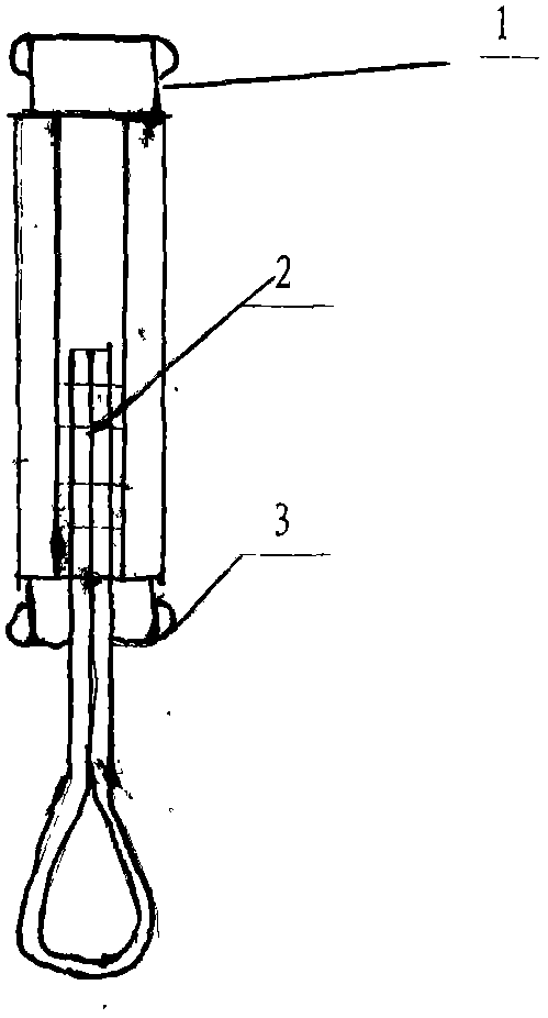
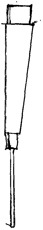
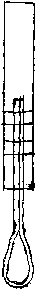
[0011] The present invention will be described in further detail below in conjunction with the accompanying drawings

[0012] like figure 1 , figure 2 , image 3 , Figure 4 As shown in the figure, the special fixed wire puller for optical cables includes a fixed groove 1, a fixed rod 2, and an anti-skid pad 3. It is characterized in that: the anti-skid pad 3 is a concave-convex long strip structure, and the width of both ends is greater than the width of the bottom edge of the fixed groove 1. And in the fixing groove 1; the fixing groove 1 is a long U-shaped structure with one end high and the other low, and the upper edges of both sides are folded inward; the fixing rod 2 is penetrated by the high end of the fixing groove 1 and pulled out from the low end.

[0013] It should be understood that the above detailed description of the improved technical solution of the present invention by means of preferred examples is illustrative rather than restrictive. Those skilled in...


PUM


Abstract

This invention discloses a special fixing wire grip for an optical cable, comprising a fixing groove (1), a fixing rod (2) and an anti-skid mat. The special fixing wire grip for the optical cable is characterized in that: the antiskid mat (3) is in a concave-convex ling strip structure and widths of two ends of the antiskid mat are greater than the width of the bottom edge of the fixing edge (1) and the antiskid mat is positioned within the fixing groove (1); the fixing groove (1) is in a long-stripe-u-shaped structure one end of which is high and the other end of which is low, and the upper edges of the two sides are folded inwardly; the fixing rod (2) is inserted into the groove (1) through the one high end of the fixing groove (1) and is pulled out from the one low end of the fixing groove. The special fixing wire grip for the optical cable is advantageous in that the cost of the finished product is low, the construction cost is greatly reduced, operation is easy, additional construction fittings are not required, assembly is fast, the wastage of the optical cable is reduced after usage, and the taking rate of users is greatly increased.

Description

technical field [0001] The invention belongs to an auxiliary device for fixing optical cables, in particular to a special fixing wire puller for optical cables. Background technique [0002] With the continuous development of existing communication technologies, optical communication has become the mainstream of the communication industry. In recent years, the FTTH solution has become popular, and the optical fiber cable is widely used as an indispensable accessory. In use, the optical cable has the characteristics of not being too stretched and deformed, so it needs to be fixed every other section. Now the project Most of them are directly fixed on the wall using cable ties or porcelain gourds, which have a certain impact on the transmission loss of the optical cable. SUMMARY OF THE INVENTION [0003] In view of the above-mentioned deficiencies of the prior art, the present invention provides an optical cable with the characteristics of simple operation and convenient us...

Claims


Application Information

Patent Timeline
IPC IPC(8): G02B6/44
Inventor 孙增民
Owner 孙增民
Why Eureka
Try Eureka