High-resolving force optical zoom lens with large target surface

A technology of optical zoom and large target area, applied in optics, optical components, installation, etc., can solve the problem that the image quality cannot meet the market demand, and achieve high-quality effects

Inactive Publication Date: 2014-05-07
FUZHOU DEV ZONE HONGFA OPTOELECTRONICS TECH
View PDF4 Cites 11 Cited by
  • Summary
  • Abstract
  • Description
  • Claims
  • Application Information

AI Technical Summary

Problems solved by technology

[0002] With the development of the security industry, people's requirements for video surveillance are getting higher and higher, and the image quality of tr

Method used


Image

  • High-resolving force optical zoom lens with large target surface
  • High-resolving force optical zoom lens with large target surface
  • High-resolving force optical zoom lens with large target surface

Examples


Embodiment Construction

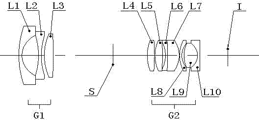
[0028] Such as figure 1 As shown, the first lens group G1 of this patent has the first lens arranged in sequence on the object side as a convex-concave lens L1, the second lens as a bi-concave lens L2 and the third bi-convex lens L3. The second lens group G2 of this patent has the fourth lens arranged in order on one side of the object as a biconvex lens L4, the fifth lens as a biconvex lens L5, the sixth lens as a concave-convex lens L6, and the seventh lens as a concave-convex lens L7. The eighth lens is a convex-convex lens L8, the ninth lens is a bi-convex lens L9, and the tenth lens is a concave-convex lens L10. The sixth lens L6 and the seventh lens L7 are cemented components, and the ninth lens L9 and the tenth lens L10 are cemented components. The zoom of 4.5-14.0mm is realized by moving the second lens group G2; by moving the first lens group G1, the position change of the image plane after zooming is compensated to ensure that the position of the image plane can be ...


PUM

PropertyMeasurementUnit
Field of viewaaaaaaaaaa
Relative apertureaaaaaaaaaa

Abstract

The invention relates to a high-resolving force optical zoom lens with a large target surface, and belongs to the field of optical and mechanical integration. The high-resolving force optical zoom lens with the large target surface sequentially comprises a first lens group G1 with negative power, a diaphragm and a second lens group G2 with positive power from an object side to an image side. The focal length of the lens is charged through moving the second lens group G2, and the change of the position of the zoomed image surface is compensated through moving the first lens group G1 to ensure that the position of the inner image surface within the whole zooming range is unchangeable. The target surface of the optical zoom lens is 1/2 cun, wherein the cun is a unit of length. In the whole focal length section, values of an optical modulation transfer function (MTF) of the lens are all more than 0.3 at a place of 1301p/mm, which ensures that the resolving force can realize high definition corresponding to mega pixel within the whole focal length section, thereby adapting to the development tendency of a security industry, and having wide market prospects.

Description

technical field [0001] This patent belongs to the field of optical-mechanical integration, and relates to an optical zoom lens, especially an optical zoom lens with a large target surface and high resolution. Background technique [0002] With the development of the security industry, people have higher and higher requirements for video surveillance. The image quality of traditional standard definition can no longer meet the market demand. In recent years, the security surveillance market has gradually developed to high-definition. In this context, many foreign CMOS chip manufacturers and scientific research institutions have invested a lot of energy to continuously improve and perfect the production process of CMOS chips, and launched a series of large target surfaces such as 1 / 2.7 inch, 1 / 2.5 inch, and 1 / 2 inch. The high-pixel CMOS chip has greatly increased the demand for large target area and high-resolution surveillance lenses in the security market. Through optical de...

Claims


Application Information

Patent Timeline
IPC IPC(8): G02B15/177G02B7/02G02B7/04
Inventor 陈金发郑志明周明东
Owner FUZHOU DEV ZONE HONGFA OPTOELECTRONICS TECH
Why Eureka
Try Eureka