Eureka AIR delivers breakthrough ideas for toughest innovation challenges, trusted by R&D personnel around the world.

Spatial light modulator and its light field three-dimensional display system

A technology of spatial light modulator and light, which is applied in optics, instruments, optical components, etc., can solve the problems of complex liquid crystal process and difficulty in mass production, and achieve high resolution, large reproduction depth, and high deflection accuracy Effect

Inactive Publication Date: 2016-10-05
SHANGHAI JIAOTONG UNIV
View PDF6 Cites 0 Cited by
  • Summary
  • Abstract
  • Description
  • Claims
  • Application Information

AI Technical Summary

Problems solved by technology

Secondly, because the liquid crystal is made on a triangular substrate, a matching layer is required, and the process of introducing liquid crystal is very complicated, so it is difficult to achieve mass production

Method used


Image

  • Spatial light modulator and its light field three-dimensional display system
  • Spatial light modulator and its light field three-dimensional display system
  • Spatial light modulator and its light field three-dimensional display system

Examples


Embodiment 1

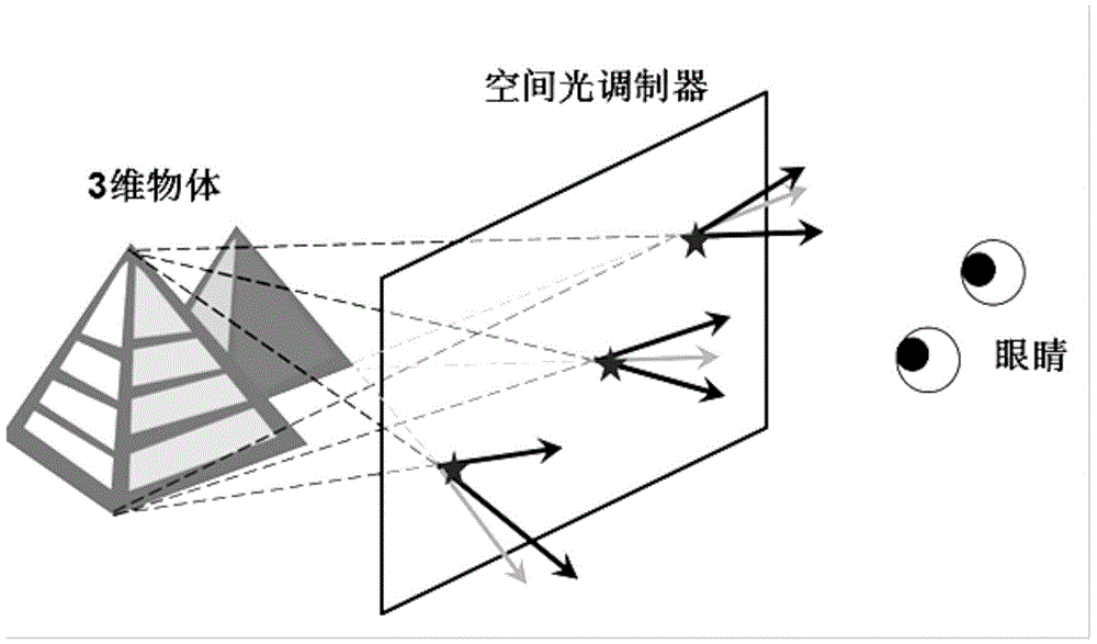
[0050] like figure 1 Shown is the principle diagram of the light field display in this embodiment; in this embodiment: the spatial light modulator 11 simulates the light emitted by the three-dimensional object 10 through each pixel unit 12 to reproduce a three-dimensional image.

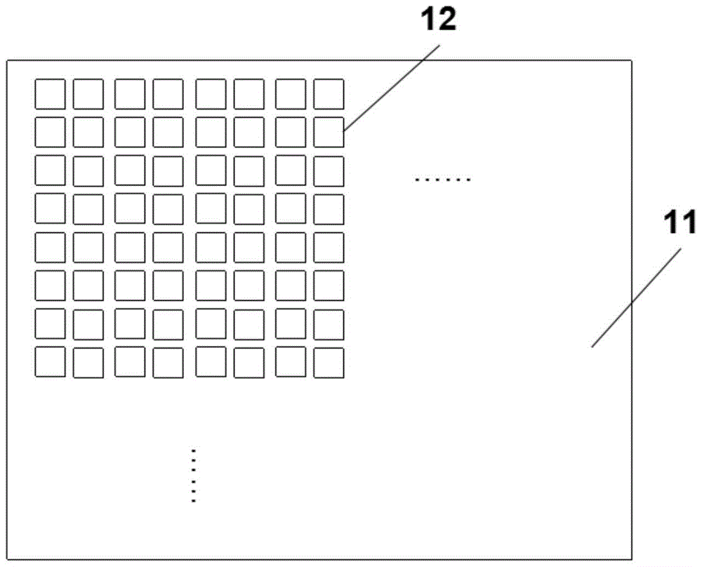
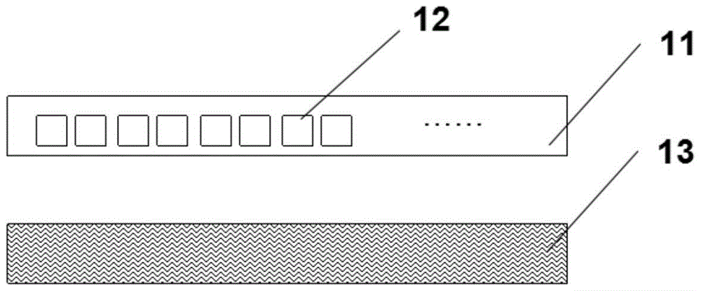
[0051] like figure 2 and image 3 As shown, the spatial light modulator 11 is a two-dimensional array composed of pixel units 12 . image 3 It is another overall structure diagram of the spatial light modulator, wherein: the spatial light modulator 11 is a one-dimensional array composed of pixel units 12, which is expanded into a simulated two-dimensional array in cooperation with the mechanical scanning device 13.

[0052] like Figure 4 As shown, each pixel 12 of the spatial light modulator is an intensity modulator 14 and a light deflector 15 . When the light emitted by the light source 13 passes through the spatial light modulator, its intensity and direction are modulated by 14 and 15 respe...

Embodiment 2

[0064] Figure 10 is the structure of the blue-phase liquid crystal light deflector in the second example figure 1 . The blue phase liquid crystal 20 is sandwiched between the upper substrate 16 and the lower substrate 17 . Inside the upper substrate 16 are triangular first electrodes 18 and triangular third electrodes 23 , and inside the lower substrate 17 are triangular second electrodes 19 and triangular fourth electrodes 24 . The triangular first electrode 18 is complementary in shape to the triangular third electrode 23, but separated by a distance of 10 microns to 5 mm. The triangular second electrode 19 is complementary in shape to the triangular fourth electrode 24, but separated by a distance of 10 microns to 5 mm. The light propagates along the z direction, parallel to the upper substrate 16 and the lower substrate 17 . The first electrode 18 and the second electrode 19 are aligned, and the angle between their hypotenuse and the light propagation direction is θ ...


PUM

PropertyMeasurementUnit
thicknessaaaaaaaaaa
thicknessaaaaaaaaaa
thicknessaaaaaaaaaa

Abstract

The invention discloses a spatial light modulator and a light field three-dimensional display system thereof, belonging to the technical field of naked eye three-dimensional display. The spatial light modulator is implemented by adopting a two-dimensional array and an analog two-dimensional array consisting of a one-dimensional array and a one-dimensional scanning mechanical device connected with the one-dimensional array, and each pixel in the array is controlled by using a light ray deflector. The light field three-dimensional display system comprises a light source module and the spatial light modulator connected with the light source module. The spatial light modulator has the advantages of large deflection angle, high deflection accuracy and quick response, and light field three-dimensional display with a large visual angle, large representation depth and high resolution is realized.

Description

technical field [0001] The invention relates to a device in the technical field of naked-eye stereoscopic display, in particular to a spatial light modulator and a light field three-dimensional display system thereof. Background technique [0002] In recent decades, display technology has developed by leaps and bounds, performance such as contrast ratio, viewing angle, resolution, and color fidelity are getting higher and higher, and volume and weight are getting smaller and smaller. However, traditional display devices can only provide two-dimensional flat images, lacking depth information (third dimension). The surrounding real world is three-dimensional, and two-dimensional display limits the perception and understanding of the complex real world. Three-dimensional display has gradually become a new development trend in the display field. [0003] Light field 3D display is an important 3D display technology. The light field display reconstructs the light field distribut...

Claims


Application Information

Patent Timeline
Patent Type & Authority Patents(China)
IPC IPC(8): G02F1/29G02B27/22
Inventor 李燕苏翼凯荣娜陈超平陆建钢吴佳旸高武然
Owner SHANGHAI JIAOTONG UNIV
Why Eureka
Eureka Blog
Learn More