Photoresponsive polymer optical fiber and preparation method and application thereof

A photoresponse, polymer technology, applied in cladding fibers, optical waveguides, optical waveguide coupling, etc., can solve the problems of rising optical loss coefficient, limited applications, and inability to precisely control the distribution of gold nanoparticles

Active Publication Date: 2020-06-19
PEKING UNIV
View PDF6 Cites 3 Cited by
  • Summary
  • Abstract
  • Description
  • Claims
  • Application Information

AI Technical Summary

Problems solved by technology

Related reports include a liquid crystal elastomer fiber doped with gold nanoparticles designed by Ryan C. Hayward et al. However, the doping process cannot precisely control the distribution of gold nanoparticles, and its photothermal effect is only sensitive in the 500-600 nanometer band. Moreover, the increase in optical loss coefficient caused by doping also limits its application as an optical switch in optical transmission systems.

Method used


Image

  • Photoresponsive polymer optical fiber and preparation method and application thereof
  • Photoresponsive polymer optical fiber and preparation method and application thereof
  • Photoresponsive polymer optical fiber and preparation method and application thereof

Examples


Embodiment 1

[0044] 1. Preparation of photoresponsive optical fiber:

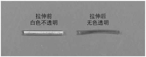
[0045] Take 300mg mesogen RM257, 72mg chain extender EDDET, 14.4mg crosslinking agent PETMP, 3mg visible light initiator Irgacure 784, mix well, add 90μL dichloromethane as a solvent, place in an oven at 70 degrees Celsius, keep warm for 5 minutes, and form A homogeneous stable solution was allowed to cool to room temperature. Add 30 μL of 2wt% DPA dichloromethane solution, vortex and mix, quickly add to a cylindrical mold with an inner diameter of 1 mm, and place at room temperature for 12 hours to form a prepolymer. Open the mold to obtain a white opaque cylinder, stretch it to a strain of 150%, and illuminate it with a wavelength of 460nm for 10 minutes (light intensity is 50mW / cm 2 ), a transparent cylindrical liquid crystal elastomer can be obtained, such as image 3 As shown, it can be used as the inner core of the optical fiber.

[0046]

[0047]

[0048] To prepare the outer cladding, take 285mg mesogen...

Embodiment 2

[0054] 1. Preparation of photoresponsive optical fiber:

[0055] Preparation of the inner core: take 300mg mesogen RM257, 72mg chain extender EDDET, 14.4mg crosslinker PETMP, 3mg UV photoinitiator HHMP, mix well, add 90μL dichloromethane as solvent, and place in an oven at 70 degrees Celsius Within 5 minutes, a homogeneous and stable solution was formed and cooled to room temperature. Add 30 μL of 2wt% DPA dichloromethane solution, vortex and mix, quickly add to a cylindrical mold with an inner diameter of 1 mm, and place at room temperature for 12 hours to form a prepolymer.

[0056] Preparation of the outer cladding: take 285mg mesogen RM257, 8.2mg photoresponsive group DR1A, 72mg chain extender EDDET, 14.4mg crosslinking agent PETMP, 3mg ultraviolet photoinitiator HHMP (photoresponsive group DR1A accounts for RM257 and 5% of the total molar weight of DR1A, and ensure that the cross-linking density of the outer cladding and the inner core is the same), after mixing evenly, ...


PUM

PropertyMeasurementUnit
diameteraaaaaaaaaa
elastic modulusaaaaaaaaaa
thicknessaaaaaaaaaa

Abstract

The invention discloses a photoresponsive polymer optical fiber and a preparation method and application thereof, and belongs to the field of optical fiber communication and sensing. According to thephotoresponsive polymer optical fiber, a uniaxially oriented liquid crystal elastomer is used as an inner-layer fiber core, a liquid crystal elastomer doped with a photoresponsive group is used as anouter cladding, and the outer cladding can sense an optical signal transmitted in the inner-layer fiber core and make a volume deformation response to a specific wavelength so as to change an overalloptical path. The deflection degree of the optical path is influenced by optical fiber structure parameters, transmission light wavelength and intensity. The photoresponsive polymer optical fiber canbe used for preparing a self-recognition mobile optical fiber type optical switch, and is applied to the fields of sensing, detection, filtering and the like.

Description

technical field [0001] The invention relates to optical fiber mobile optical switch technology, in particular to an optical fiber that undergoes mechanical deformation when transmitting light of a specific wavelength and its preparation method and application, belonging to the field of optical fiber communication and sensing. Background technique [0002] Optical fiber technology has brought revolutionary breakthroughs and developments to the communication industry, but the explosive growth of communication business demands has also put forward new requirements for the management and control technology of optical fiber networks. An optical switch is an optical path conversion device, which can realize the switching connection of the optical path, and has important applications in the fields of optical cross-connect system, optical fiber transmission and testing. [0003] The types of optical switches can be divided into traditional mechanical optical switches, micro-mechanic...

Claims


Application Information

Patent Timeline
Patent Type & Authority Applications(China)
IPC IPC(8): G02B6/02G02B6/35C08G75/045D06M15/63D06M101/30
CPCC08G75/045D06M15/63D06M2101/30G02B6/02033G02B6/3504
Inventor 于海峰马树灯
Owner PEKING UNIV
Why Eureka
Try Eureka