display device
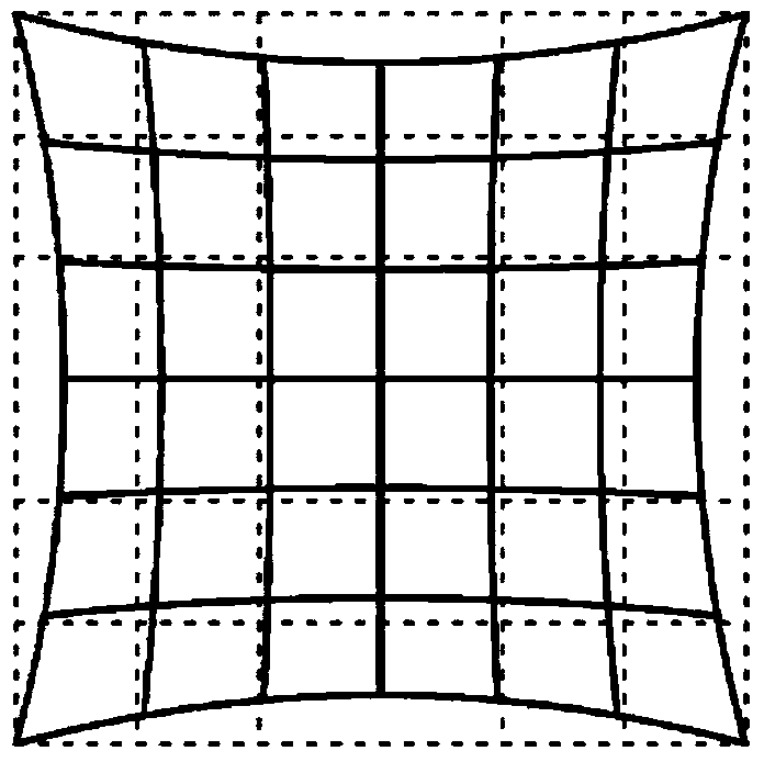
A technology of display device and image display device, applied in image enhancement, instrument, television and other directions, can solve the problems of image distortion, image resolution cannot become uniform, etc.
- Summary
- Abstract
- Description
- Claims
- Application Information
AI Technical Summary
Problems solved by technology
Method used
Image
Examples
no. 1 example
[0078] The first embodiment relates to the display device according to the first embodiment of the present invention. More specifically, the first embodiment relates to the binocular type display device of the present invention, the display device of the first configuration of the present invention, and the display device of the third configuration of the present invention. image 3 It illustrates a perspective view of the main part of the display device when the observer is wearing the display device. Figure 4 The figure shows a plane mirror and the like included in the optical system of the image display device for the right eye when viewed in the x-axis direction. Figure 5 A conceptual diagram (perspective view) of the image forming apparatus and optical system when viewed from the observer side is shown. Image 6 A conceptual diagram (perspective view) of the image forming apparatus and optical system when viewed from above is illustrated. and, Figure 7A Illustrated is a p...
no. 2 example
[0127] The second embodiment is a modification of the first embodiment. Figure 13A A schematic cross-sectional view of the supporting member and the image forming device included in the image display device of the second embodiment is illustrated. Figure 13B A schematic cross-sectional view of the support member is illustrated. Figure 13C A schematic plan view of the supporting member and the image forming apparatus is illustrated. Figure 13D Illustrated along the supporting member and the image forming device Figure 13A A schematic cross-sectional view of arrow D-D in.
[0128] In the image display device of the second embodiment, the peripheral portion of the image forming device 40 extending in the X direction is supported by the member 60 2 Holding on. Support member 60 2 It includes a lower member 66A and an upper member 66B. The combination of the lower side member 66A and the upper side member 66B constitutes a kind of frame member. In support member 60 2 On the inner...
no. 3 example
[0131] The third embodiment is a modification of the second embodiment. In the third embodiment, the image forming apparatus 40 is also curved. However, unlike the second embodiment, the degree of bending can be changed. Figure 14A A schematic cross-sectional view of the supporting member and the image forming device included in the image display device of the third embodiment is illustrated. Figure 14B A schematic plan view of the supporting member and the image forming apparatus is illustrated.
[0132] In the third embodiment, there is a gap between the groove portion 66C and the peripheral portion of the image forming device 40 extending in the X direction. Then, in the support member 60 3 On the side surface extending in the X direction, a protrusion 67A and a threaded portion 67B are provided. Support member 60 3 It is housed in a housing (not shown), and the upper part of the housing is open. The housing is attached to the upper part of each of the frame bodies 53R and...
PUM
 Abstract
Description
Claims
Application Information
 - R&D
- Intellectual Property
- Life Sciences
- Materials
- Tech Scout
- Unparalleled Data Quality
- Higher Quality Content
- 60% Fewer Hallucinations
Browse by: Latest US Patents, China's latest patents, Technical Efficacy Thesaurus, Application Domain, Technology Topic, Popular Technical Reports.
© 2025 PatSnap. All rights reserved.Legal|Privacy policy|Modern Slavery Act Transparency Statement|Sitemap|About US| Contact US: help@patsnap.com


