NFC antenna and apparatus

An antenna, the other side of the technology, applied in the field of mobile POS machine devices, can solve the problems of unsophisticated, weakened antenna sensitivity, large machine appearance, etc., and achieve the effect of simple appearance

Inactive Publication Date: 2014-05-07
深圳市九思泰达技术有限公司
View PDF4 Cites 7 Cited by
  • Summary
  • Abstract
  • Description
  • Claims
  • Application Information

AI Technical Summary

Problems solved by technology

[0003] In the existing NFC antenna design, FPC (flexible circuit board) soft board is mostly used, but when this kind of antenna is close to the metal, the metal will absorb the antenna signal, resulting in weakened antenna sensitivity, or eve

Method used


Image

  • NFC antenna and apparatus
  • NFC antenna and apparatus
  • NFC antenna and apparatus

Examples


Embodiment Construction

[0019] Specific embodiments of the present invention will be described in detail below in conjunction with the accompanying drawings.

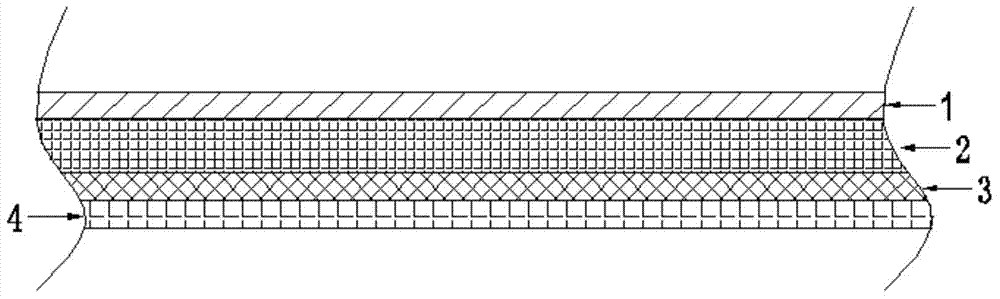
[0020] Such as figure 1 As shown, an NFC antenna according to the present invention is composed of an FPC (flexible circuit board) 1 and a ferrite sheet 2, and the FPC is attached to one side of the ferrite sheet to form an integral body with the FPC. Specifically, the ferrite sheet is pasted on the FPC by double-sided adhesive tape.

[0021] In order to facilitate the installation of the NFC antenna, an adhesive body is attached to the other side of the ferrite sheet 2 , which is a double-sided adhesive tape 3 with a release paper 4 in this embodiment.

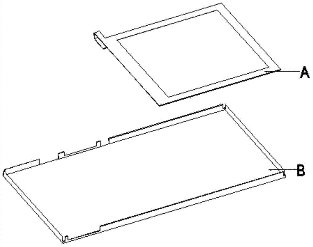
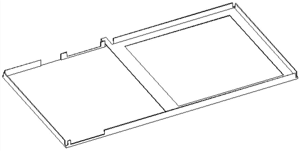
[0022] Such as figure 2 As shown, there is a mobile device with an NFC antenna A. The NFC antenna A is composed of an FPC and a ferrite sheet. The FPC is attached to one side of the ferrite sheet. In order to facilitate the fixing of the antenna, the ferrite sheet On the other side there ...


PUM


Abstract

The invention discloses an NFC antenna. The NFC antenna is composed of an FPC and a ferrite slice. The FPC is attached to one side of the ferrite slice to form an integral body with the ferrite slice. According to the invention, the problems of approach incapability of a conventional NFC antenna or attachment of the conventional NFC antenna to a metal are solved, and the NFC antenna and the screen of a mobile device are combined together so that the product space is saved.

Description

technical field [0001] The invention relates to an NFC antenna and a mobile POS device provided with the NFC antenna. Background technique [0002] NFC antenna is the abbreviation of short-range communication. It is a short-distance high-frequency wireless communication technology that allows non-contact point-to-point data transmission and exchange data between electronic devices. It is widely used in the field of mobile payment. [0003] In the existing NFC antenna design, FPC (flexible circuit board) soft board is mostly used to make it. However, when this antenna is close to metal, the metal will absorb the antenna signal, resulting in weakened antenna sensitivity or even ineffectiveness. Therefore, in the product design, the NFC antenna cannot be designed inside the machine, resulting in a large and unsophisticated machine, or the position of the antenna cannot be placed randomly, which affects the product design. Contents of the invention [0004] The invention prov...

Claims


Application Information

Patent Timeline
IPC IPC(8): H01Q1/36H01Q1/24G07G1/00
Inventor 陆智孙士友穆敬东程世强
Owner 深圳市九思泰达技术有限公司
Why Eureka
Try Eureka