
Vehicle control apparatus

A technology of control device and braking device, which is applied in the direction of power unit, vehicle components, engine control, etc., and can solve problems such as inability to start control.

Active Publication Date: 2014-05-07
TOYOTA JIDOSHA KK
View PDF9 Cites 2 Cited by
  • Summary
  • Abstract
  • Description
  • Claims
  • Application Information

AI Technical Summary

Problems solved by technology

Therefore, when such a failure occurs, the start control cannot be performed in response to the driver's driving shift operation.

Method used


Image

  • Vehicle control apparatus
  • Vehicle control apparatus
  • Vehicle control apparatus

Examples


Embodiment Construction

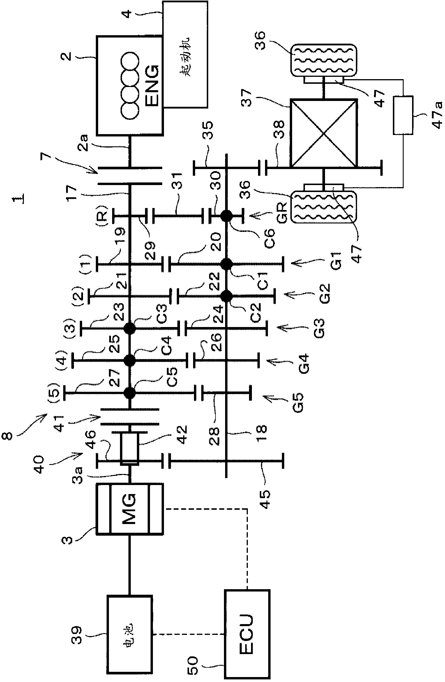
[0022] Such as figure 1 As shown, a vehicle 1 is configured as a so-called hybrid vehicle in which an internal combustion engine 2 and a motor generator 3 as an electric motor are provided as power sources for traveling. A starter device 4 used for start control is provided in the internal combustion engine 2 . The configuration of the starter device 4 is the same as a known configuration, and thus description thereof will be omitted.

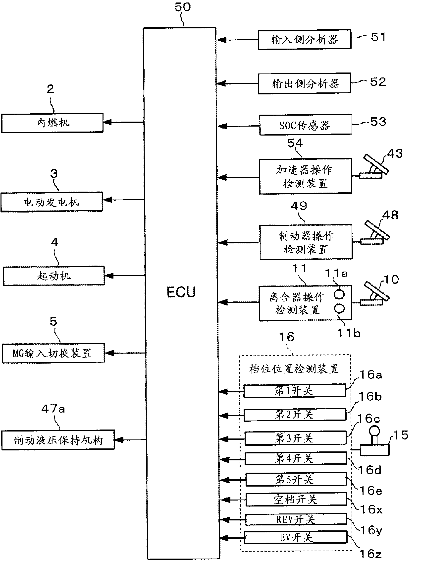
[0023] The internal combustion engine 2 is configured as a spark ignition type internal combustion engine. An output shaft 2 a of the internal combustion engine 2 is connected to a manual transmission 8 via a clutch 7 . The clutch 7 is disposed between the internal combustion engine 2 and the manual transmission 8, and is operated by a driver as a clutch pedal 10 (see figure 2 ). When the clutch pedal 10 is released by the driver, torque transmission between the internal combustion engine 2 and the manual transmission 8 is cut off. A clut...


PUM


Abstract

A control apparatus according to the present invention is applied to a hybrid vehicle with a manual transmission. The control apparatus, when a neutral switch is outputting a detection signal with an internal combustion engine stopped and the vehicle at a halt (S31, S32), controls a motor generator such that the manual transmission is supplied with torque (S35 to S39), and starts the internal combustion engine in accordance with a releasing operation for the clutch when the time rate of change (S40) of the input side rotating speed of the manual transmission as a result of torque providing control does not satisfy a predetermined reference.

Description

technical field [0001] The present invention relates to a control device applicable to a vehicle equipped with an internal combustion engine and an electric motor as driving power sources and equipped with a manual transmission operated by a driver. Background technique [0002] There is known a hybrid vehicle in which torques of an internal combustion engine and an electric motor are output as driving power sources via a manual transmission. As such a vehicle control device, there is known a device for estimating, from the input / output rotation speeds of a manual transmission, which gear stage has been selected among a plurality of stepped gear stages included in the manual transmission (Patent Document 1). In addition, there are Patent Documents 2 and 3 as prior art documents related to the present invention. [0003] Patent Document 1: Japanese Patent Laid-Open No. 2001-221330 [0004] Patent Document 2: Japanese Patent Laid-Open No. 2007-255566 [0005] Patent Documen...

Claims


Application Information

Patent Timeline
IPC IPC(8): B60W30/18B60W20/00B60W10/02B60W10/06B60W10/11B60K6/48B60K6/547F02D17/00B60L50/16
CPCB60K6/48B60K6/547B60W10/02B60W10/06B60W10/11B60W20/40B60W20/50B60W30/18054F02D17/00B60W2510/101B60W2510/102B60W2510/0652Y02T10/62Y10S903/93B60W10/08B60W20/10
Inventor 服部勉
Owner TOYOTA JIDOSHA KK
Learn More