
Quick Die Change Device

A fast and fixed device technology, applied in metal processing equipment, forming tools, manufacturing tools, etc., can solve the problems of difficult mold cores to be fixed in a fixed position and not to be replaced.

Inactive Publication Date: 2015-08-26
金牌模具(常熟)有限公司
View PDF7 Cites 0 Cited by
  • Summary
  • Abstract
  • Description
  • Claims
  • Application Information

AI Technical Summary

Problems solved by technology

For this reason, the applicant has searched the literature, and the Chinese invention patent application publication number CN101607438A recommends a "simple and fast mold change device". However, because it is aimed at injection molding molds with relatively small specifications, there is no technical inspiration for the replacement of cold stamping molds for stamping relatively large specifications such as LCD TV backplanes
Furthermore, the authorized announcement number CN201618788U provides "a quick mold change device". Although this patent solution is proposed for the mold change of cold stamping dies, it is only suitable for small-sized hardware stamping dies, because when the mold specifications When it is large, it is difficult to reliably fix the mold core in the fixed position by fasteners

Method used


Image

  • Quick Die Change Device
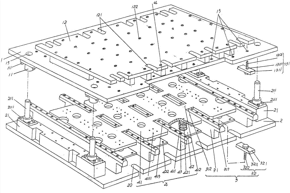
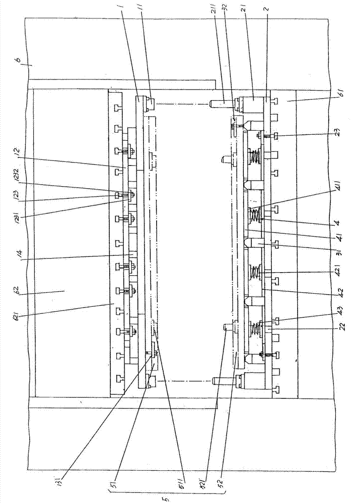
  • Quick Die Change Device

Examples


Embodiment

[0022] In the following descriptions, all concepts involving up, down, left, right, front and back direction positions are aimed at figure 1 As far as the position status shown is concerned, the purpose is to facilitate the understanding of the public, so it should not be construed as a limitation on the technical content of the present invention.

[0023] Please see figure 1 , provides an upper formwork plate 1 and a lower formwork plate 2 which are made of metal materials and are rectangular, that is, a cuboid. In the state of use, the upper formwork plate 1 is used for the figure 2 The schematic stamping device 6 such as the punch 62 of the hydraulic press is fixedly connected to the cylinder column (the connection device connected with the upper mold frame plate 1 is provided on the oil cylinder column, such as the punch upper table 621), and the lower mold frame plate 2 is in use. under and by figure 2 The punching operation platform 61 (also called the working table)...


PUM


Abstract

The invention relates to a rapid die replacing device, and belongs to the technical field of dies. The rapid die replacing device comprises an upper die frame plate and a lower die frame plate, upper die frame plate guide parts are fixed to the side, facing toward the lower die frame plate, of the upper die frame plate and located on the four corners of the upper die frame plate respectively, an upper die frame fixing plate is arranged on the side, back on to the lower die frame plate, of the upper die frame plate, a pair of lower die frame plate guide part fixing bases is arranged on the side, facing toward the upper die frame plate, of the lower die frame plate, the pair of lower die frame plate guide part fixing bases is respectively fixedly provided with a pair of lower die frame plate guide parts corresponding to the upper die frame plate guide parts, and the upper die frame plate guide parts are in slide fit with the lower die frame plate guide parts; a pair of lower die clamping mechanisms is arranged on the side, facing toward the upper die frame plate, of the lower die frame plate, located between one pair of lower die frame plate guide part fixing bases and parallel to the lower die frame plate guide part fixing bases. Accessory cost of a die set can be substantially reduced, resources can be saved, and the rapid die replacing device is high in die replacing speed and well adaptive to clamping of dies of different specifications.

Description

technical field [0001] The invention belongs to the technical field of moulds, and in particular relates to a quick mold changing device, which is used for quick replacement of cold stamping molds. Background technique [0002] For small molds such as injection molds, there are usually standard mold bases, so there is no confusion when changing molds. However, for stamping dies with many batches, small batches, and large specifications, such as cold stamping dies used for stamping LCD TV backplanes (also called display backplanes) of different specifications, if they are equipped with standard mold bases, it is easy to cause A significant increase in the cost of the entire set of molds, and a serious waste of resources. It is precisely based on this factor that at present, large-scale cold stamping dies with limited batch stamping quantities are not equipped with separate standard mold bases. The advantages are: it can significantly reduce the cost of complete sets of molds...

Claims


Application Information

Patent Timeline
Patent Type & Authority Patents(China)
IPC IPC(8): B21D37/04
Inventor 刘为民朱国凯
Owner 金牌模具(常熟)有限公司
Learn More