Train pantograph logical intelligent control system based on intelligent control units

A technology of intelligent control unit and intelligent control system, applied in general control system, program control in sequence/logic controller, control/regulation system, etc., can solve problems such as waste of manpower and material resources, high protection cost, and increase of renovation cost. , to achieve the effect of saving renovation costs and reducing maintenance costs in the later period

Active Publication Date: 2019-12-03
CRRC QINGDAO SIFANG CO LTD
View PDF5 Cites 4 Cited by
  • Summary
  • Abstract
  • Description
  • Claims
  • Application Information

AI Technical Summary

Problems solved by technology

[0002] In the EMU pantograph logic control circuit, due to the large number of relays involved, the risk of a single point failure causing the failure of the entire system increases. At the same time, due to the many protection conditions involved, the circuit structure is more complicated
At present, if it is necessary to transform the pantograph logic control, it is necessary to carry out line transformation on the basis of the original circuit. This transformation may involve the discarding and remanufacturing of the circuit board or the modification of the external wiring, which wastes manpower and material resources and increases the transformation cost.
Secondly, for the current structure of vehicle logic control, all printed circuit boards have the risk of burning, and the protection to avoid burning is all concentrated on the side of the circuit breaker. If there is a problem and the circuit breaker trips, there will be a In the case of large-area logic control circuit failure, it is too expensive to protect each circuit with the current technology

Method used


Image

  • Train pantograph logical intelligent control system based on intelligent control units
  • Train pantograph logical intelligent control system based on intelligent control units

Examples


Embodiment Construction

[0030] In order to make the purpose, technical solutions and advantages of the embodiments of the present invention clearer, the technical solutions in the embodiments of the present invention will be clearly and completely described below in conjunction with the drawings in the embodiments of the present invention. Obviously, the described embodiments It is a part of embodiments of the present invention, but not all embodiments. Based on the embodiments of the present invention, all other embodiments obtained by persons of ordinary skill in the art without creative efforts fall within the protection scope of the present invention.

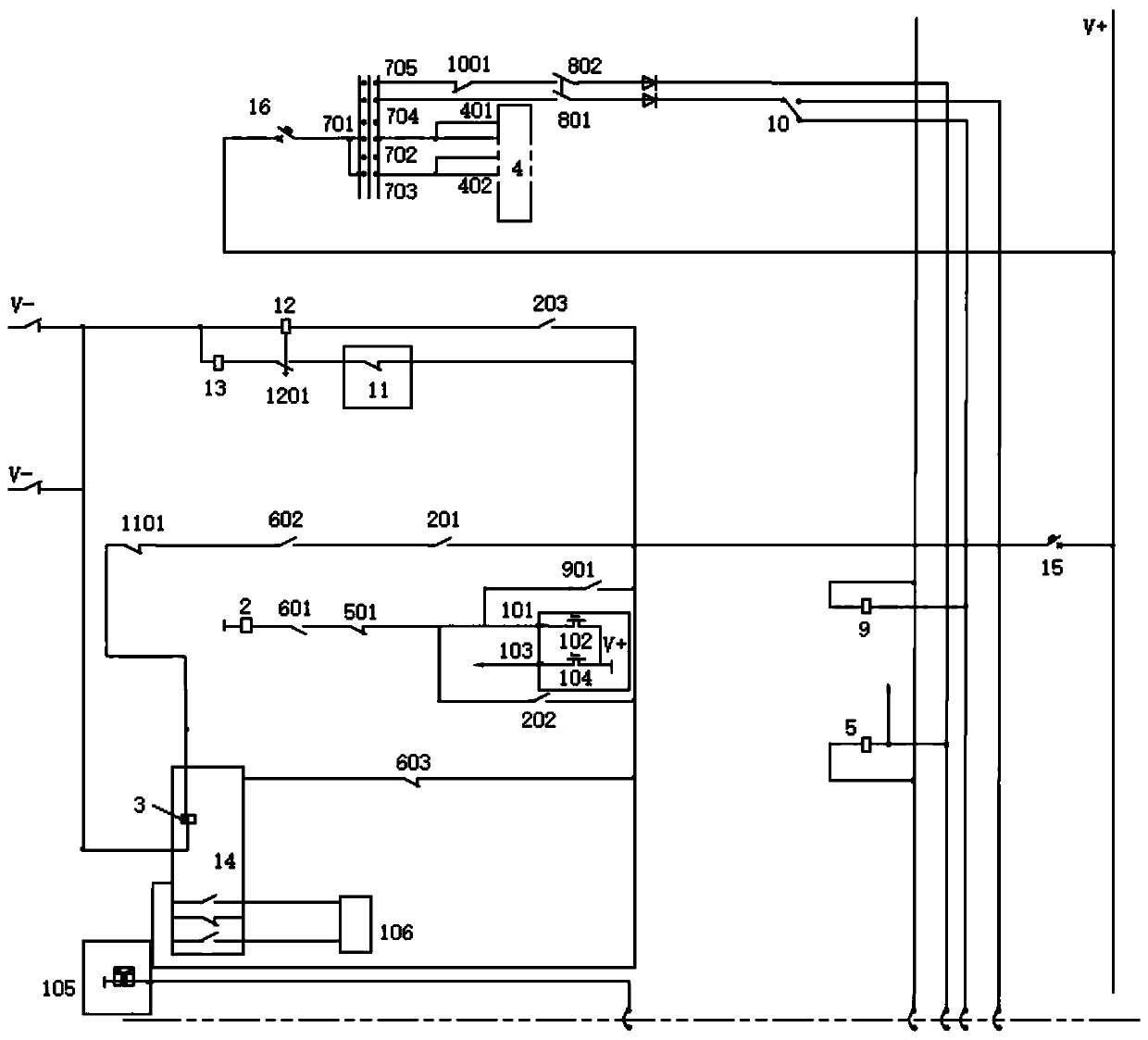
[0031] figure 1 It is a schematic diagram of the electrical structure of the train pantograph logic intelligent control system based on the intelligent control unit provided by the embodiment of the present invention. Such as figure 1 As shown, the system includes: an intelligent control unit, a lifting bow execution relay 2, a lifting bow solen...


PUM


Abstract

The invention provides a train pantograph logical intelligent control system based on intelligent control units. The train pantograph logical intelligent control system based on the intelligent control units comprises the intelligent control units, a pantograph rising execution relay, a pantograph rising electromagnetic valve and a train network unit. After the intelligent control units receive apantograph rising instruction sent by the train network unit, the intelligent control units control a first electronic switch to close, the pantograph rising execution relay is electrified, a first contact point of the pantograph rising execution relay is closed, the pantograph rising electromagnetic valve is electrified, and a pantograph rises. The train pantograph logical intelligent control system based on the intelligent control units realizes control for the pantograph by using the intelligent control units of an LCU (logic control unit) and the like as a control core, solves the problemsthat an existing D-series high-speed train set relay logical control circuit is complex, contact points are abnormally adhered together, a circuit board is burnt and the like at present, saves designand use remolding, late maintenance and spare part cost, improves reliability and realizes circuit simplification for the high-speed train set logical control circuit, and improves late maintenance and remolding efficiency.

Description

technical field [0001] The invention relates to the technical field of automatic control, in particular to a train pantograph logic intelligent control system based on an intelligent control unit. Background technique [0002] In the EMU pantograph logic control circuit, due to the large number of relays involved, the risk of single point failures leading to the failure of the entire system increases. At the same time, due to the many protection conditions involved, the circuit structure is more complicated. At present, if the transformation of pantograph logic control is required, it is necessary to carry out line transformation on the basis of the original circuit. This transformation may involve the discarding and remanufacturing of circuit boards or the modification of external wiring, which wastes manpower and material resources and increases the transformation cost. Secondly, for the current structure of vehicle logic control, all printed circuit boards have the risk o...

Claims


Application Information

Patent Timeline
Patent Type & Authority Applications(China)
IPC IPC(8): B60L5/28G05B19/05
CPCB60L5/28G05B19/058
Inventor 蒋博文梁建英周建升林森岳同奇
Owner CRRC QINGDAO SIFANG CO LTD
Why Eureka
Try Eureka