Suspension device for tunnels

A technology for suspension devices and tunnels, which is applied to mining devices, mining equipment, earthwork drilling and mining, etc. It can solve the problems of affecting the service life, not being able to increase or decrease the specifications of the pre-buried channels, and being fixed.

Inactive Publication Date: 2015-09-16
SHANDONG TECHGONG GEOTECHN ENG EQUIP CO LTD
View PDF5 Cites 12 Cited by
  • Summary
  • Abstract
  • Description
  • Claims
  • Application Information

AI Technical Summary

Problems solved by technology

[0003] In order to solve the above problems, in recent years, during the construction process, the tunnel concrete segments have been added with pre-embedded channels, and the components to be installed are fixed by T-bolts, but there are also a series of problems. The tunnel concrete segments are used During the process, it will be affected by the stray flow to produce electrochemical corrosion. The main object of electrochemical corrosion is the steel bar with a complete segment structure. As the corrosion reaction continues, the corrosion products will continue to increase, thereby destroying the segment structure. During the process of pouring the tunnel into the segment, it will be in contact with the steel cage inside the segment, which increases the steel structure contact surface of the tunnel concrete segment, and is more likely to cause electrochemical corrosion due to the influence of maze during use. The position of the channel is fixed after pouring into the tunnel concrete segment, and the specification of the pre-embedded channel cannot be increased or decreased according to the actual engineering requirements. In addition, when there are few pre-embedded channels, manual drilling is required in the later stage. Both damage the structure of the segment and affect the service life

Method used


Image

  • Suspension device for tunnels
  • Suspension device for tunnels
  • Suspension device for tunnels

Examples


example

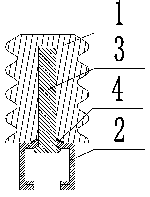
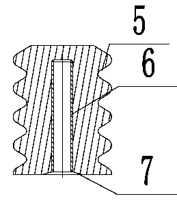
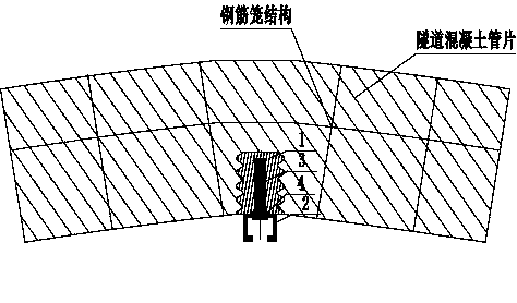
[0013] The following describes in detail a specific implementation example of the new type of the present invention, see image 3 , A suspension device for a tunnel is composed of embedded casing 1, toothed channel 2, countersunk screws 3, and elastic gasket 4. During construction, the embedded casing 1 is pre-cast in the tunnel concrete segments, and the cast The position is in the gap of the concrete segment reinforcement cage of the tunnel, the toothed channel 2 is connected to the inner arc surface of the tunnel concrete segment by the tightening fit of the countersunk screw 3 and the embedded casing 1, avoiding the embedded casing, The toothed channel is in direct contact with the steel cage structure in the tunnel concrete segment. The embedded casing 1 occupies a small space in the tunnel concrete segment and has little impact on the main structure of the tunnel concrete segment. The countersunk screw 3 An elastic washer 4 is installed between the bottom and the bottom 7...


PUM


Abstract

The invention discloses a suspension device for tunnels. The suspension device mainly comprises an embedded sleeve, a toothed slot, a countersunk head screw and an elastic gasket, wherein the embedded sleeve is cast in a tunnel concrete duct piece in advance, the casting position is in the clearance part of the reinforcement cage structure of the tunnel concrete duct piece, the toothed slot and the embedded sleeve, by use of the countersunk head screw, are cooperatively connected with the inner arc surface of the tunnel concrete duct piece or in a semi-inlaid arrangement on the inner arc surface of the tunnel concrete duct piece, so as to prevent the embedded sleeve and the toothed slot from being in contact with the reinforcement cage structure of the tunnel concrete duct piece. The electrochemical corrosion on the main structure of the tunnel by stray current can be effectively lightened, the destruction on the main structure of the tunnel concrete duct piece by manual drilling and expansion bolts in the prior art can be prevented, the construction efficiency in tunnels can be increased, the proper specification of the toothed slot can be selected according to the concrete engineering requirements, the toothed slot can be conveniently replaced, the maintenance cost and the operation cost can be reduced, and the service life of the tunnel concrete duct piece can be prolonged.

Description

Technical field [0001] The invention relates to a suspension device for tunnels, in particular to a toothed channel suspension device. Background technique [0002] At present, during the construction of subway tunnels, most of the installation of pipelines and equipment on the concrete segments of the tunnel adopts the traditional manual drilling method, which is installed with expansion bolts on the drilling. This installation method is not only low in work efficiency, but also when drilling. The position of the hole encounters the steel bar, which makes it impossible to drill to the standard depth, and the anchoring depth is not enough, which brings safety hazards. It may even damage or break the steel bar due to drilling, destroy the main structure of the tunnel concrete segment, and cause difficulty in later reinforcement. The construction efficiency of the tunnel is affected, and the maintenance is also difficult, which affects the service life of the subway. [0003] In ord...

Claims


Application Information

Patent Timeline
Patent Type & Authority Applications(China)
IPC IPC(8): E21F17/02
Inventor 张学强郭峰王刚闫国成武成义刘德然孙金壮宋迎德袁立磊田思君
Owner SHANDONG TECHGONG GEOTECHN ENG EQUIP CO LTD
Why Eureka
Try Eureka