Train door logic intelligent control system based on intelligent control unit

A technology of intelligent control unit and intelligent control system, which is applied in door/window accessories, wing leaf operating mechanism, buildings, etc., can solve problems such as high protection cost, printed circuit board burnout, logic control circuit failure, etc., and achieve The effect of reducing maintenance costs and saving renovation costs in the later period

Active Publication Date: 2020-01-03
CRRC QINGDAO SIFANG CO LTD
View PDF8 Cites 2 Cited by
  • Summary
  • Abstract
  • Description
  • Claims
  • Application Information

AI Technical Summary

Problems solved by technology

[0002] In the EMU door logic control circuit, due to the large number of relays involved, the risk of a single point of failure leading to the failure of the entire system is increased. At the same time, due to the large number of involved doors, the vehicle penetration cable structure is more complicated
At present, if it is necessary to carry out the transformation of the door logic control, it is necessary to carry out circuit transformation on the basis of the original circuit. This transformation may involve the discarding and remanufacturing of the circuit board or the modification of the external wiring.
Secondly, for the current structure of vehicle logic control, all printed circuit boards have the risk of burning, and the protection to avoid burning is all concentrated on the side of the circuit breaker. If there is a problem and the circuit breaker trips, there will be a In the case of large-area logic control circuit failure, it is too expensive to protect each circuit with the current technology

Method used


Image

  • Train door logic intelligent control system based on intelligent control unit
  • Train door logic intelligent control system based on intelligent control unit
  • Train door logic intelligent control system based on intelligent control unit

Examples


Embodiment Construction

[0019] In order to make the purpose, technical solutions and advantages of the embodiments of the present invention clearer, the technical solutions in the embodiments of the present invention will be clearly and completely described below in conjunction with the drawings in the embodiments of the present invention. Obviously, the described embodiments It is a part of embodiments of the present invention, but not all embodiments. Based on the embodiments of the present invention, all other embodiments obtained by persons of ordinary skill in the art without creative efforts fall within the protection scope of the present invention.

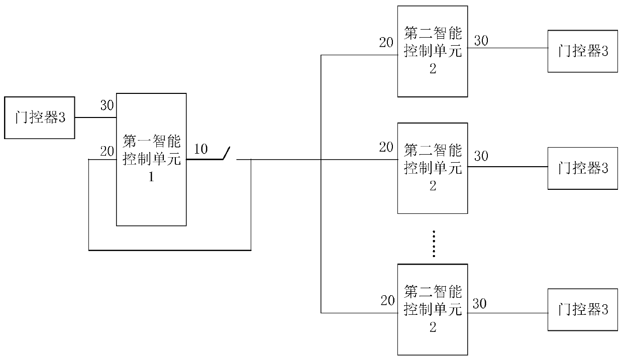
[0020] figure 1 It is a schematic diagram of the principle of the train door logic intelligent control system based on the intelligent control unit provided by the embodiment of the present invention. like figure 1 As shown, the system includes a first intelligent control unit 1 located in the selected vehicle, a second intelligent control unit ...


PUM


Abstract

The embodiment of the invention provides a train door logic intelligent control system based on an intelligent control unit. The train door logic intelligent control system comprises a first intelligent control unit, second intelligent control units and door controllers, wherein the first intelligent control unit is located on a selected vehicle, the second intelligent control units are located atthe rest of the vehicles, and the door controllers are located at all the vehicles; after the first intelligent control unit acquires door control operation information, and the corresponding door control instruction is output through the corresponding door control instruction output ports; after the corresponding door control instruction input ports of the first intelligent control unit and thesecond intelligent control units receive the door control instruction, the corresponding door controller control ports are driven to control the door controllers of the vehicles to execute the door control instruction. According to the train door logic intelligent control system based on the intelligent control unit provided by the embodiment of the invention, through the use of a contactless control system, the problems of complex logic control circuit, abnormal contact adhesion, circuit board burning loss and the like of a current multiple unit relay are solved, meanwhile, the cost is saved,the circuit is simplified, and the maintenance efficiency is improved.

Description

technical field [0001] The invention relates to the technical field of automatic control, in particular to a train door logic intelligent control system based on an intelligent control unit. Background technique [0002] In the EMU door logic control circuit, due to the large number of relays involved, the risk of a single point failure leading to the failure of the entire system is increased. At the same time, due to the large number of involved doors, the vehicle penetration cable structure is more complicated. At present, if it is necessary to modify the logic control of the car door, it is necessary to carry out circuit modification on the basis of the original circuit. This modification may involve the discarding and remanufacturing of the circuit board or the modification of the external wiring. Secondly, for the current structure of vehicle logic control, all printed circuit boards have the risk of burning, and the protection to avoid burning is all concentrated on th...

Claims


Application Information

Patent Timeline
Patent Type & Authority Applications(China)
IPC IPC(8): E05F15/70E05B77/54
CPCE05F15/70E05B77/54E05Y2900/531E05Y2900/51E05Y2400/40E05Y2400/456E05Y2800/21
Inventor 张安梁建英蒋博文孙传铭施孟阳
Owner CRRC QINGDAO SIFANG CO LTD
Why Eureka
Try Eureka