Novel steel ladle lifting synchronous control system

A synchronous control and ladle technology, applied in the direction of fluid pressure actuators, servo motors, servo motor components, etc., can solve the problems of high manufacturing cost, heavy maintenance workload, high operating cost, etc., and achieve low installation difficulty, simple transformation, The effect of high control precision

Inactive Publication Date: 2015-11-04
CHINA NAT HEAVY MACHINERY RES INSTCO
View PDF8 Cites 4 Cited by
  • Summary
  • Abstract
  • Description
  • Claims
  • Application Information

AI Technical Summary

Problems solved by technology

During the ladle lifting process, because each lifting hydraulic cylinder 2 lifts heavy weight and fast speed, the known synchronous motor 4 usually adopts a large-flow synchronous motor to meet the working condition requirements of the ladle lifting hydraulic cylinder 2, so the manufacturing cost is expensive; At the same time, in the process of use, if any one of the synchronous motors 4 has a problem, the synchronous motor 4 needs to be replaced as a whole, so the maintenance workload is large, and the cost of spare parts and operating costs are very high.

Method used


Image

  • Novel steel ladle lifting synchronous control system
  • Novel steel ladle lifting synchronous control system

Examples


Embodiment Construction

[0017] The present invention will be described in further detail below in conjunction with the accompanying drawings.

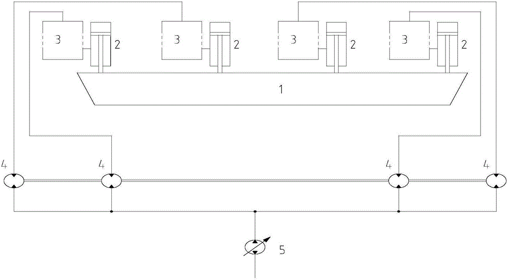
[0018] Such as figure 1 As shown, the specific structure of the known traditional ladle lifting synchronous control system is:

[0019] The ladle 1 filled with molten steel is lifted to the processing position required by the molten steel treatment process by four ladle lifting hydraulic cylinders 2. During the lifting process of the ladle, the four hydraulic cylinders are required to work synchronously to ensure the safety and reliability of the molten steel lifting and processing process; position The locking device 3 can safely and reliably lock the ladle lifting hydraulic cylinder 2 at any position; when the large-flow synchronous motor 4 is working, it distributes the flow from the hydraulic main pump 5 to each ladle lifting hydraulic cylinder 2 equally, so that the flow into the ladle lifting hydraulic cylinder 2 flow is equal to ensure that the four l...


PUM


Abstract

The invention discloses a novel steel ladle lifting synchronous control system. The novel steel ladle lifting synchronous control system comprises four steel ladle lifting hydraulic cylinders, position locking devices, proportional valves, a hydraulic main pump, position detection devices and synchronous electric control devices, wherein the four steel ladle lifting hydraulic cylinders are arranged on a steel ladle, the position locking devices and the proportional valves are connected with the steel ladle lifting hydraulic cylinders respectively, the hydraulic main pump is connected with the four proportional valves, the position detection devices are mounted on the steel ladle lifting hydraulic cylinders respectively, and the synchronous electric control devices are connected with the position detection devices and the proportional valves. The steel ladle is synchronously lifted through the four steel ladle lifting hydraulic cylinders. The lifting position of the steel ladle is controlled through the proportional valves. The position of the steel ladle is detected in real time through the position detection devices. The synchronous electric control devices can independently control the opening degrees of the corresponding proportional valves in real time according to actual values fed back by the position detection devices and automatically control the flow flowing to the steel ladle lifting hydraulic cylinders from the hydraulic main pump through the proportional valves, and thus it is guaranteed that the steel ladle is lifted synchronously. According to the novel steel ladle lifting synchronous control system, the synchronous lifting control function that four lifting hydraulic cylinders are controlled through existing large-flow synchronous motors connected in parallel is replaced with the function that the lifting hydraulic cylinders are independently controlled through the proportional valves, and accordingly the defects in the prior art are overcome.

Description

technical field [0001] The invention relates to the technical field of vacuum smelting of molten steel, in particular to a novel ladle lifting synchronous control system. Background technique [0002] In the existing molten steel vacuum smelting technology, in order to reduce the turnover time of the ladle and improve the vacuum treatment efficiency of the molten steel, the ladle lifting synchronous control system is applied to the molten steel treatment link. The ladle trolley transports the ladle to the molten steel treatment station along the running track, and the lifting device lifts the ladle from the ladle trolley to the processing height required by the process. After the vacuum treatment of molten steel is completed, the lifting device lowers the ladle to the running track On the ladle trolley, the ladle trolley transports the ladle away from the molten steel treatment position and enters the next process link. This ladle lifting form, because the ladle is lifted i...

Claims


Application Information

Patent Timeline
Patent Type & Authority Applications(China)
IPC IPC(8): F15B13/04F15B13/00
CPCF15B11/22
Inventor 丘铭军郭星良张永锋陈国防
Owner CHINA NAT HEAVY MACHINERY RES INSTCO
Why Eureka
Try Eureka