
Automatic disinfection and drying device

A drying device and automatic disinfection technology, which can be applied to other drying devices, washing devices, household dryers, etc., can solve the problem of long working time, and achieve the effect of improving convenience.

Active Publication Date: 2015-12-30
新疆北辰高新电子科技有限公司
View PDF12 Cites 0 Cited by
  • Summary
  • Abstract
  • Description
  • Claims
  • Application Information

AI Technical Summary

Problems solved by technology

[0004] The purpose of the present invention is to provide a fully automatic disinfection and drying device to solve the technical problem of long working time in the aforementioned existing disinfection and drying devices

Method used


Image

  • Automatic disinfection and drying device
  • Automatic disinfection and drying device
  • Automatic disinfection and drying device

Examples


Embodiment 1

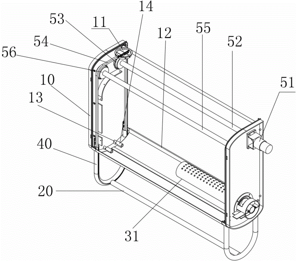
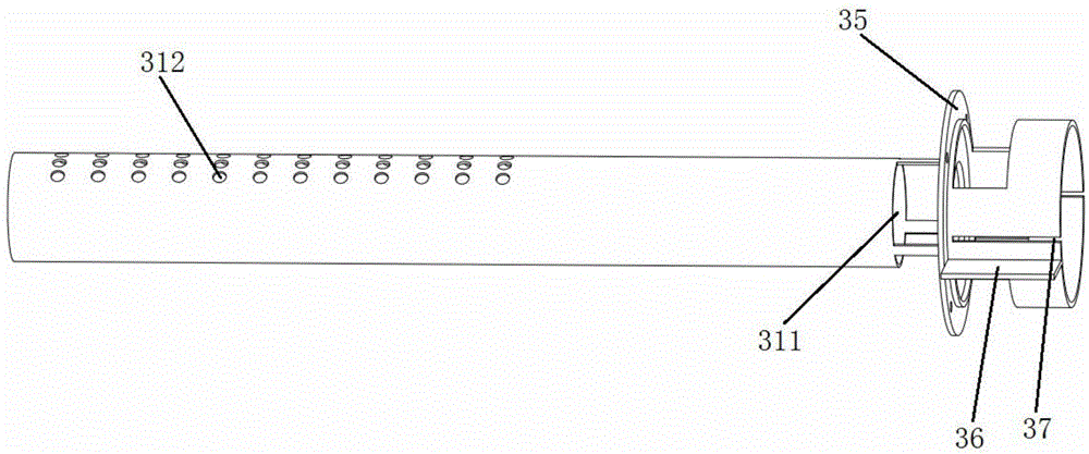
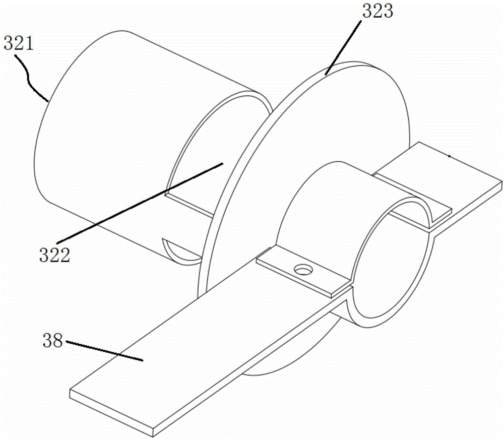
[0051] Such as figure 1 As shown, a specific embodiment of a fully automatic disinfection and drying device is provided, the device includes a box body 10, a power module (not shown in the figure), an electric control system (not shown in the figure) and a heating system, Objects to be sterilized and dried, such as towels and clothes, can be accommodated in the box body 10. The power supply module is used to supply power to the electric control system and the heating system, and the electric control system is used to control the heating The system is disinfected and dried. Please refer to Figure 1 to Figure 5 , the heating system includes an outer air duct 31, an inner air duct 32, an electric heater (not shown in the figure) and a fan 33, wherein: the outer air duct 31 is arranged inside the box body 10 and on the wall of the outer air duct 31 A first opening 311 is provided, and the electric heater is arranged in the outer air duct 31 for heating the air. The electric hea...

Embodiment 2

[0075] Compared with Embodiment 1, the difference of this embodiment is only in the structure of the outer air duct 31 and related structures for realizing the relative movement between the inner air duct 32 and the outer air duct 31 .

[0076] Such as Figure 9 As shown, the outer air duct 31 of this embodiment is not provided with the flange 35 as described in Embodiment 1, but a mounting screw hole 301 is provided at one end of the outer air duct 31, so that the outer air duct 31 is directly installed by screws. On the side wall of the box body 10, as in the embodiment, the position corresponding to the side wall of the box body 10 and the inner air duct 32 is provided with a hole for the inner air duct to pass through; The support structure of the inner air duct, the support structure includes a support 102 and an inner tube slider 103 fixed on the outside of the side wall of the box body 10, the support 102 is provided with a slide rail matched with the inner tube slider ...


PUM


Abstract

An automatic disinfecting and drying device for disinfecting and drying towels and clothes; the device comprises a box (10), a power supply module, an electronic control system and a heating system; towels and clothes are placed in the box (10); the electronic control system controls the heating system to disinfect and dry the towels and the clothes at a high temperature; the heating system comprises an outer air pipe (31), an inner air pipe (32), a heating wire and a fan (33); the heating wire is disposed in the outer air pipe (31); the outer air pipe (31) is disposed in the box (10), and is provided with a first opening (311); the inner air pipe (32) has a first end (321) and a second end respectively located outside and inside the outer air pipe (31); the first end is open, and the second end is provided with a wind deflector (323); the inner air pipe (32) is provided with a second opening (322). The electronic control system controls the relative movement of the inner air pipe and the outer air pipe to form two working positions; when the relative movement causes the first opening (311) to overlap with the second opening (322), air circulating through the heating wire within the box (10) can quickly raise the temperature of the box (10) for disinfection; and when the relative movement causes the openings to be offset from each other, air circulation through the heating wire is formed inside and outside the box (10) , thus quickly heating and drying the interior of the box (10).

Description

technical field [0001] The invention relates to household appliances and sanitary equipment, in particular to an automatic disinfection and drying device which can be used to disinfect and dry towels, clothes and the like. Background technique [0002] There is a multi-functional towel rack (abbreviated as machine) among the common towel and toothbrush disinfection appliances on the market. The machine includes an electric control device, an ultraviolet toothbrush disinfection device, an aluminum drying heating plate inside the body, a PTC steam generating device, a movable panel, an upper cover and a horizontal bar for hanging towels. The machine uses manual opening of the upper cover and panel to add water to the machine, stack the towels on the aluminum heating plate inside the machine, close the panel and upper cover, press the disinfection switch button, and the PTC heater at the bottom will The water is heated to boiling to generate steam, and steam sterilization star...

Claims


Application Information

Patent Timeline
Patent Type & Authority Patents(China)
IPC IPC(8): D06F58/10A61L2/06A61L2/10
CPCD06F58/16A47K10/06D06F57/12
Inventor 江川
Owner 新疆北辰高新电子科技有限公司
Features
  • Generate Ideas
  • Intellectual Property
  • Life Sciences
  • Materials
  • Tech Scout
  • Unparalleled Data Quality
  • Higher Quality Content
  • 60% Fewer Hallucinations
Learn More