
Negative pressure siphoning backflow vacuum valve

A vacuum valve and siphon technology, applied in valve details, control valves, valve devices, etc., can solve problems such as inability to open, complicated processing, and high price, and achieve the effects of high reliability, flexible cover plate, and large air supply volume

Active Publication Date: 2014-05-14
SHANGHAI SANSHENG METAL PROD
View PDF6 Cites 0 Cited by
  • Summary
  • Abstract
  • Description
  • Claims
  • Application Information

AI Technical Summary

Problems solved by technology

[0005] At present, the vacuum breaking valve is mainly produced by some foreign companies. The valve body is basically welded and cannot be opened. If there is dirt on the flow channel or sealing surface that affects the seal, it cannot be cleaned.
Its sealing structure adopts hard seal, and the sealing is realized by using the line contact between the high-roundness steel ball and the high-precision spherical surface, which requires the roundness of the ball to be very high. At the same time, the sealing surface of the valve body needs high-precision grinding, which makes the processing complicated. high cost, expensive

Method used


Image

  • Negative pressure siphoning backflow vacuum valve
  • Negative pressure siphoning backflow vacuum valve
  • Negative pressure siphoning backflow vacuum valve

Examples


Embodiment 1

[0042] Specific implementation 1. The negative pressure siphon backflow vacuum valve has a length of 55 mm and a height of 41 mm.

Embodiment 2

[0043] Specific implementation 2, the negative pressure siphon backflow vacuum valve has a length of 76 mm and a height of 62 mm.

Embodiment 3

[0044] Specific implementation 3, the negative pressure siphon backflow vacuum valve has a length of 96mm and a height of 72mm.

[0045]A piezoelectric ceramic is arranged between the valve body and the "T"-shaped cover plate, and the piezoelectric ceramic is connected to an indicator light through an electric energy storage unit. The indicator light is preferably led light. When the "T"-shaped cover plate presses down on the valve body, piezoelectric ceramics generate electricity and the indicator light is on. As a preferred solution, the vertical distance between the lower edge of the expansion port and the water outlet of the downstream pipeline is not less than 150 mm.

[0046] Beneficial effects: the present invention has high working safety and reliability, good sealing performance and no water leakage during normal use, flexible cover plate and large amount of air replenishment when replenishing air; no need for operation control, fully automatic work, using atmospheri...


PUM


Abstract

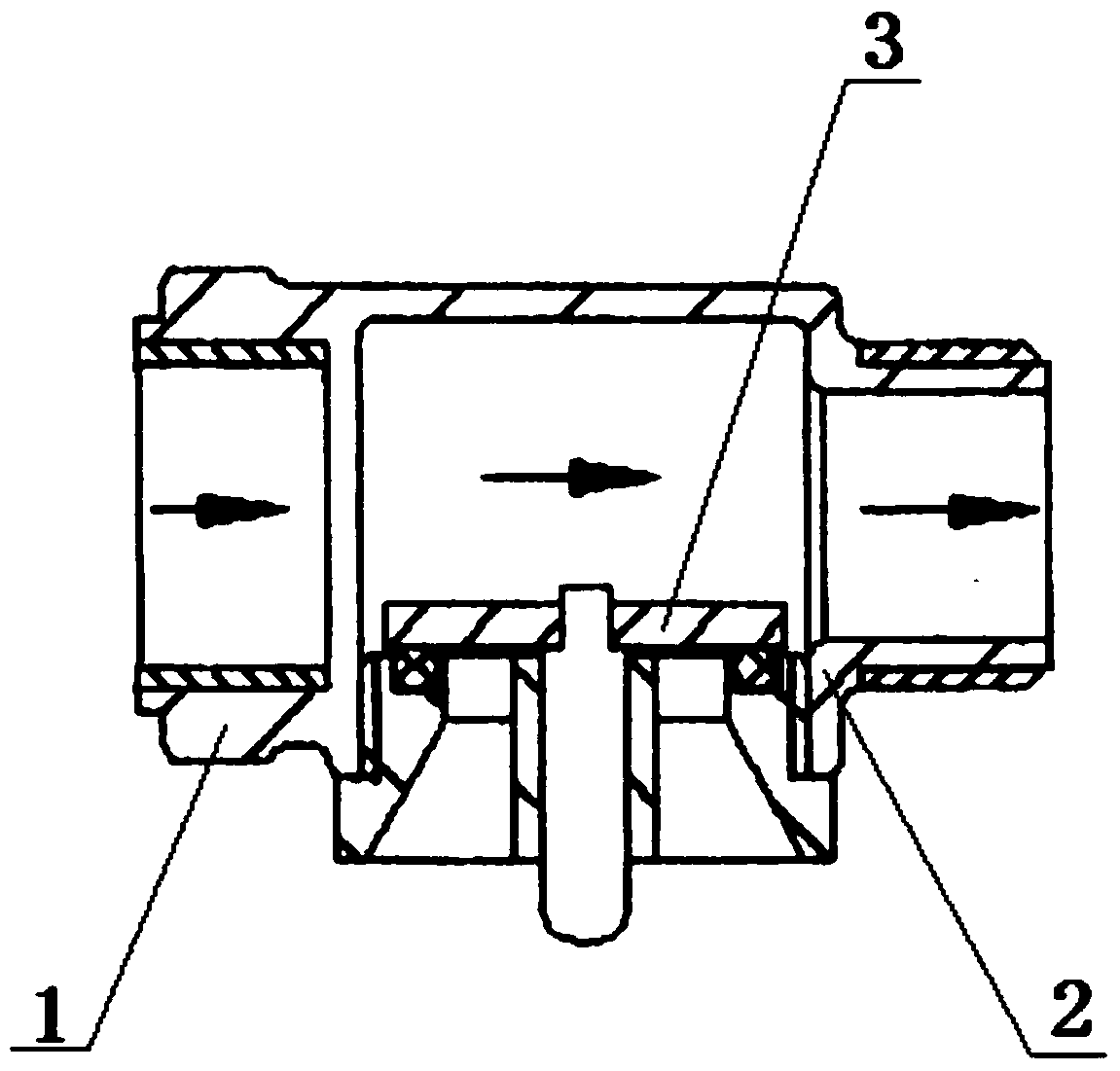
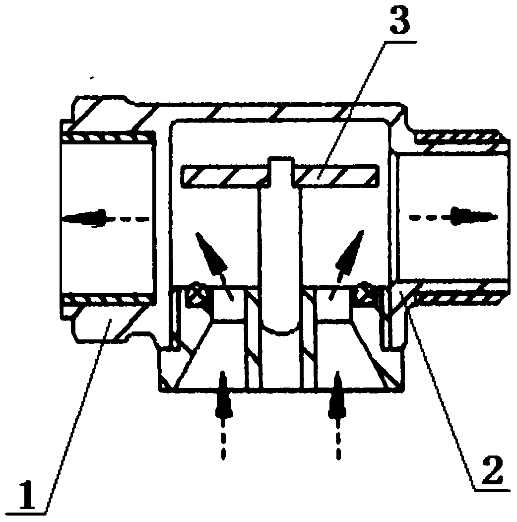
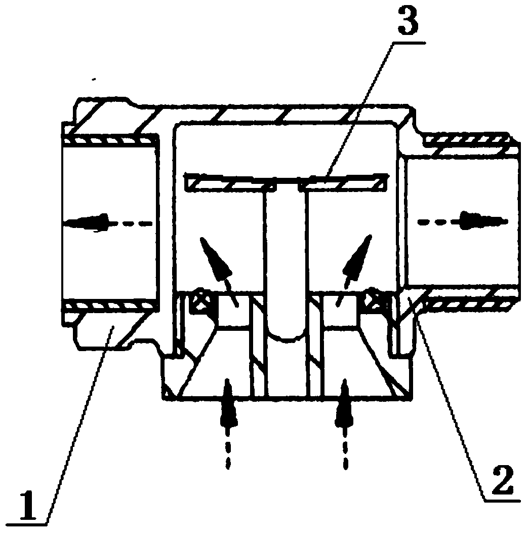
The invention relates to the technical field of valves, in particular to a vacuum breaker valve, namely a negative pressure siphoning backflow vacuum valve comprising a valve body. The left side of the valve body is provided with a first pipe orifice used for being connected with an upstream water pipe; the right side of the valve body is provided with a second pipe orifice used for being connected with a downstream water pipe. The valve body is provided with a hollow cavity inside. The negative pressure siphoning backflow vacuum valve further comprises a cover plate with T-shaped longitudinal section; the cover plate comprises a transverse plate and a vertical plate; the transverse plate is arranged inside the hollow cavity; the bottom of the hollow cavity is provided with an opening; the vertical plate extends out of the opening; the cover plate can move up and down along the opening; the bottom of the hollow cavity is further provided with a suction hole outside the opening; the transverse plate can cover and close the suction hole. The negative pressure siphoning backflow vacuum valve is capable of safely operating and high in reliability; when in normal use, the valve has good sealing performance and is free of water leakage; during air supply, the cover plate is flexible and the volume of air supply is high; operational control is not required, operation is fully automated, atmospheric pressure is used as a power source, and connecting other power sources is not required. The negative pressure siphoning backflow vacuum valve is installed with no need for debugging.

Description

technical field [0001] The invention relates to the technical field of valves, in particular to a vacuum breaking valve. Background technique [0002] In daily life, the negative pressure in the water supply pipeline will cause the water or liquid mixture in the sanitary appliance and the water receiving container to flow back into the domestic water supply system, that is, negative pressure siphon backflow. Negative pressure siphon backflow is the backflow caused by the pressure reduction or negative pressure (vacuum or partial vacuum) at the water supply end of the water supply system. For example, interruption of water supply due to firefighting, burst pipes, repairs of nearby pipe network. [0003] The deterioration of the water quality of the drinking water system due to the backflow phenomenon is called backflow pollution, also known as backflow pollution. The technical measures to prevent backflow pollution can generally adopt measures and devices such as air partit...

Claims


Application Information

Patent Timeline
Patent Type & Authority Applications(China)
IPC IPC(8): F16K15/00
CPCF16K27/00F16K51/02
Inventor 盛斌富志霞
Owner SHANGHAI SANSHENG METAL PROD
Learn More