
Manual and electric automatic separating and combining mechanism of electric actuator

An electric actuator and automatic clutch technology, which is applied in the direction of engine components, mechanical equipment, valve operation/release devices, etc., can solve problems such as easy wear of the shaft sleeve, difficulty in movement, and influence on the conversion effect of the actuator.

Active Publication Date: 2014-05-14
ZHEJIANG AOXIANG AUTO CONTROL TECH CO LTD
View PDF8 Cites 5 Cited by
  • Summary
  • Abstract
  • Description
  • Claims
  • Application Information

AI Technical Summary

Problems solved by technology

At present, most of the clutches used in the market are switched on the worm gear and worm behind the motor. In principle, the manual and electric automatic switching functions can be realized, but its biggest problem is that when switching at a place with high torque output, the action will be special. Difficult, especially when the output point is stuck, because the worm gear can provide self-locking, making it switch immovable
Moreover, in the prior art, a shaft sleeve is used at the connection between the center wheel and the ejector rod, and the shaft sleeve is prone to wear during long-term activities, so that the ejector rod will jump in the shaft sleeve, thereby affecting the conversion effect of the entire actuator

Method used


Image

  • Manual and electric automatic separating and combining mechanism of electric actuator
  • Manual and electric automatic separating and combining mechanism of electric actuator
  • Manual and electric automatic separating and combining mechanism of electric actuator

Examples


Embodiment Construction

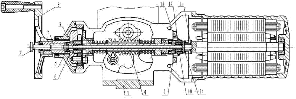
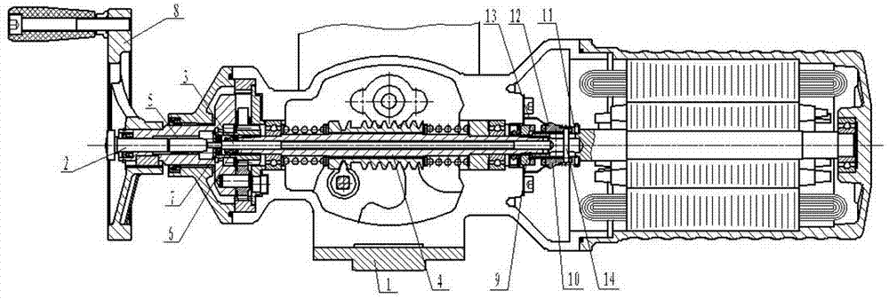
[0012] The accompanying drawings show the technical solution of the present invention and its embodiments, and the relevant details will be further described below in conjunction with the accompanying drawings. The manual and electric automatic clutch mechanism of the electric actuator includes a base 1, and the base 1 is equipped with Switching ejector rod 2, ejector rod 3, hollow shaft 4 and clutch, said switching ejector rod 2 is provided with a first elastic device 5, said first elastic device is a switching ejector rod return spring, pushing inwardly switching ejector rod 2 When switching the ejector rod 2, it will push the ejector rod 3 to move. To move, one end of the hollow shaft 4 is covered with a center wheel 6, and the hollow shaft 4 is engaged with the center wheel 6, that is, the hollow shaft 4 is provided with an external spline, and the center wheel 6 is provided with an internal spline. When the spline is engaged with the inner spline, the center wheel 6 can d...


PUM


Abstract

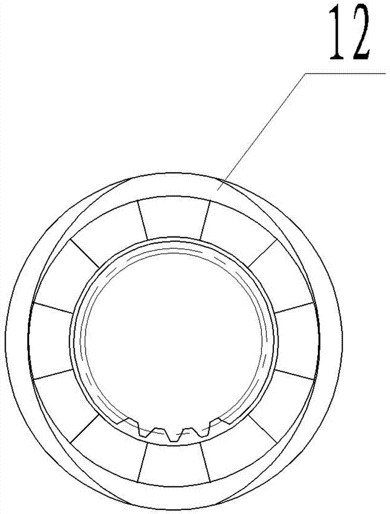
The invention discloses a manual and electric automatic separating and combining mechanism of an electric actuator. The mechanism comprises a machine base (1), and is characterized in that a switching ejector rod (2), an ejector rod (3), a hollow shaft (4) and a clutch, wherein the switching ejector rod (2), the ejector rod (3), the hollow shaft (4) and the clutch are arranged in the machine base, the ejector rod is movably arranged in the hollow shaft in the axial direction, the other end of the hollow shaft is connected with the clutch, the clutch comprises a fixed part (9) and a movable part (10), the movable part is in transmission connection with a motor shaft, the movable part is ejected when the ejector rod axially moves to the direction of a motor, the movable part is provided with a clamping portion (12), and the fixed part is provided with a snap spring elastic piece (13) matched with the clamping portion. When the movable part moves to the direction of the motor, the snap spring elastic piece deforms and abuts against the clamping portion; when the movable part rotates, the snap spring elastic piece deforms and is away from the clamping portion. The manual and electric automatic separating and combining mechanism is stable and reliable in structure, can effectively achieve switching between manual operation and electric operation, and is long in service life.

Description

technical field [0001] The invention relates to an electric actuator used for valve control, in particular to a manual and electric automatic clutch mechanism of the electric actuator. Background technique [0002] The actuator is mainly used in the automatic control of the valve, through which the valve can be automatically controlled locally or remotely, and it is widely used in petroleum, chemical and other fields. The current electric actuators generally have the problem of the stability of overload protection. Although most of the intelligent actuators are designed with manual functions, it is difficult to perfectly achieve their reliability, stability, safety and The use requirements of the clutch can be easily completed manually. If the handle is directly driven, the structure is simple, and the handle will move when the electric work is performed, which is very dangerous to use on site. At present, most of the clutches used in the market are switched on the worm g...

Claims


Application Information

Patent Timeline
Patent Type & Authority Applications(China)
IPC IPC(8): F16K31/05
CPCF16K31/05
Inventor 蔡东武
Owner ZHEJIANG AOXIANG AUTO CONTROL TECH CO LTD
Learn More