Short-crank tight-lock coupler-uncoupling device

A close-fitting and decoupling technology, which is applied in transportation and packaging, railway car body parts, railway couplings, etc., can solve the problems of small vertical space occupation and inability to equip side-hanging electrical connectors, so as to facilitate on-site operation Effect

Inactive Publication Date: 2011-05-18
CRRC QINGDAO SIFANG ROLLING STOCK RES INST
View PDF0 Cites 0 Cited by
  • Summary
  • Abstract
  • Description
  • Claims
  • Application Information

AI Technical Summary

Problems solved by technology

[0005] The purpose of the present invention is to provide a decoupling device that can keep the decoupling state of the coupler in view of the shortcomings of the existing close-connected coupler, which saves the steps of manually inserting and pulling out the limit pin, and improves the degree of automation and safety; at the same time, the uncoupling device The built-in coupler cylinder makes the layout of the coupler structure compact and reasonable, takes up less space in the longitudinal direction, and has better integration performance between the coupler and other modular units of the coupler and buffer device; and because the crank is truncated, this solution solves the problem that the prototype coupler and buffer device cannot be equipped with side cranes Type electrical connector problem

Method used


Image

  • Short-crank tight-lock coupler-uncoupling device
  • Short-crank tight-lock coupler-uncoupling device
  • Short-crank tight-lock coupler-uncoupling device

Examples


no. 1 Embodiment

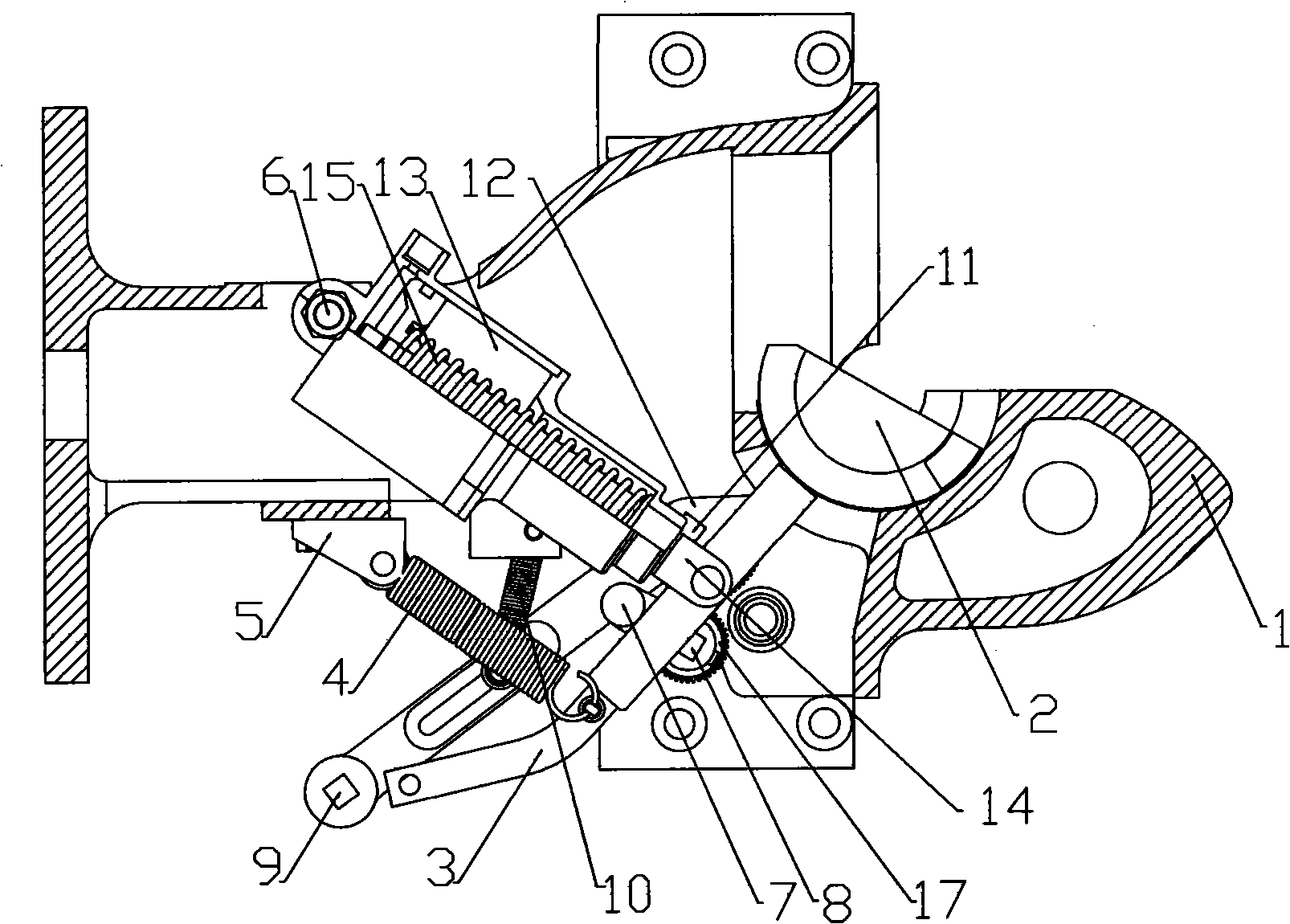
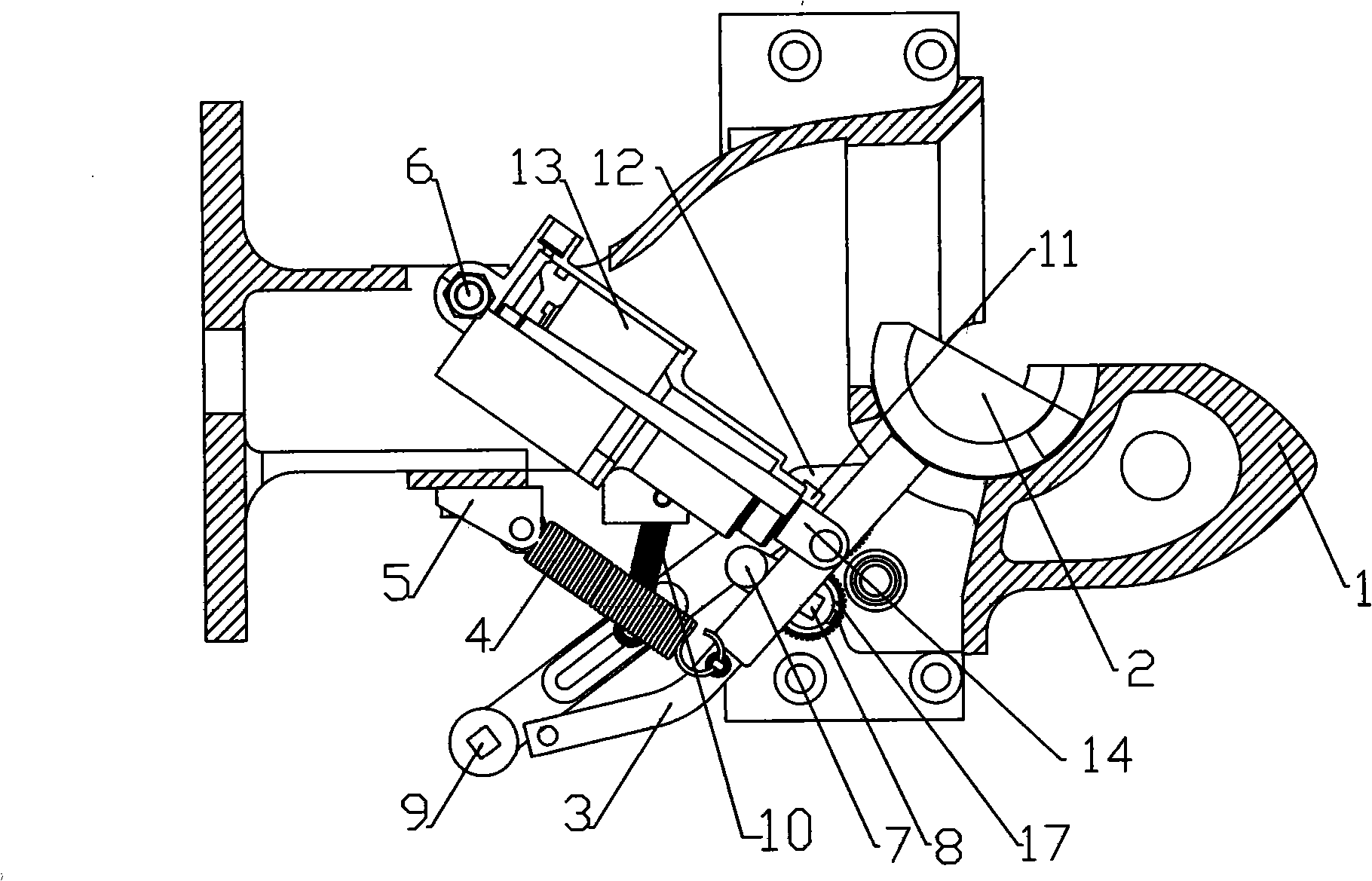
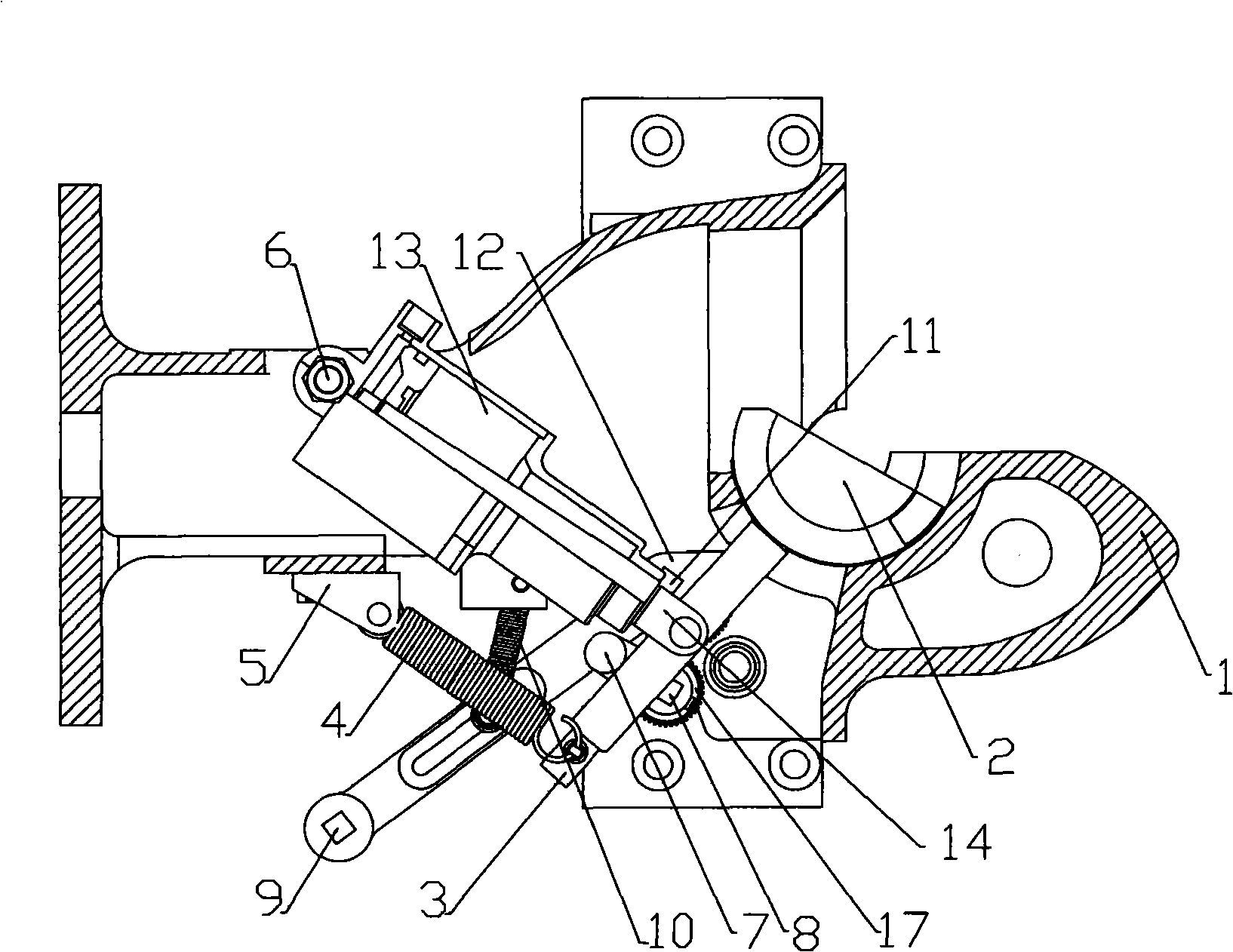
[0029] Such as figure 1 The first specific embodiment of the present invention described above: a short-crank close-contact type coupler uncoupling device, including the coupler body 1 at the front, the knuckle cavity and the knuckle cavity at the rear of the coupler body 1, and the knuckle cavity is set There is a knuckle tongue 2, an unhook crank 3 is installed on the knuckle tongue 2, and an unhook cylinder 13 and a crank return device are arranged between the unhook crank 3 and the hook body cavity. Rotatingly installed on the hook body cavity, the piston rod 14 of the unhook cylinder 13 is pinned to the middle part of the crank 3, and the unhook cylinder 13 is provided with a return spring 15; the crank return device is a crank spring 4, the crank spring 4 One end is installed on the spring attachment seat 5 at the end of the uncoupling device, and the other end is connected with the crank 3. The hook body cavity is provided with an unhook handle 9 and a bellcrank 7 link...


PUM


Abstract

The invention relates to a short-crank tight-lock coupler-uncoupling device comprising a coupler body, a coupler tongue cavity and a coupler body cavity which are all arranged at the front part. The coupler tongue cavity is internally provided with a coupler tongue, an uncoupling crank is mounted on the coupler tongue, and a crank-returning device is arranged between the uncoupling crank and the coupler body cavity which is provided with a manual uncoupling state retaining device comprising an uncoupling handle, a handle-returning device and a crank throw connected with the uncoupling handle;the crank throw glidingly contacts with the crank; and a dead point enabling the crank throw and the crank to keep relative static without external force exists on a path where the uncoupling handle drives the crank throw and the crank and further drives the coupler tongue to rotate while the coupler tongue is in an uncoupling position. The addition of the manual uncoupling state retaining devicecan still keep the uncoupling state of the coupler tongue in the uncoupling position when human force is removed, thereby omitting the step of manually plugging and pulling a spacer pin. The extending end of the crank can be also shortened to create conditions for arranging an electric connector of a side sling type on a coupler and draft gear and satisfy the requirement for automatically and electrically connecting a novel railway vehicle.

Description

technical field [0001] The invention relates to a railway vehicle equipment, in particular to an uncoupling device of a close-connected coupler for a railway vehicle. Background technique [0002] The hook and buffer device is one of the basic components of the railway vehicle, which can quickly connect and disassemble the railway vehicle, transmit the traction force of the train, improve the safety of the vehicle, and improve the comfort performance of the vehicle. [0003] The uncoupling device of the domestic close-connected coupler includes manual uncoupling and automatic uncoupling. The manual uncoupling handle is generally installed on one side of the coupler body, and the uncoupling operation is realized by manpower. The automatic uncoupling method generally adopts the structure of the uncoupling cylinder. The cylinder is longitudinally arranged on one side of the hook body or inside the hook body, and the cylinder directly drives the knuckle mechanism, and the cylind...

Claims


Application Information

Patent Timeline
Patent Type & Authority Patents(China)
IPC IPC(8): B61G3/20
Inventor 黄皖初
Owner CRRC QINGDAO SIFANG ROLLING STOCK RES INST
Why Eureka
Try Eureka