Supercharge Your Innovation With Domain-Expert AI Agents!

The Restoration Method of Aerospace Level Absolute Photoelectric Encoder Signal

A photoelectric encoder and photoelectric signal technology, which is applied in the direction of instruments, conversion sensor output, measuring devices, etc., can solve the problems that the encoder cannot work normally and can not be repaired manually, so as to overcome irreparable and improve reliability and stability , the effect of reducing workload

Inactive Publication Date: 2016-03-02
CHANGCHUN INST OF OPTICS FINE MECHANICS & PHYSICS CHINESE ACAD OF SCI
View PDF5 Cites 0 Cited by
  • Summary
  • Abstract
  • Description
  • Claims
  • Application Information

AI Technical Summary

Problems solved by technology

[0003] In order to solve the problem that the encoder cannot work normally and cannot be manually repaired when the photoelectric signal of the aerospace-grade absolute photoelectric encoder is missing, this invention proposes a repair method for the signal of the aerospace-grade absolute photoelectric encoder

Method used


Image

  • The Restoration Method of Aerospace Level Absolute Photoelectric Encoder Signal
  • The Restoration Method of Aerospace Level Absolute Photoelectric Encoder Signal
  • The Restoration Method of Aerospace Level Absolute Photoelectric Encoder Signal

Examples


specific Embodiment approach 1

[0024] Specific embodiments 1. The method for repairing the signal of the aerospace-level absolute photoelectric encoder of the present invention, the specific steps of the method are as follows:

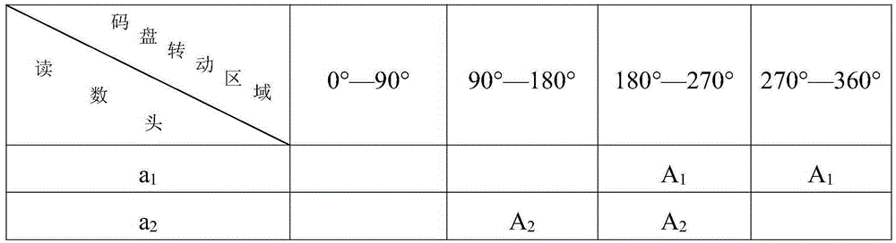
[0025] Step 1, under the condition of the matrix code disc design diagram of the known photoelectric encoder, utilize this matrix code disc design diagram, analyze the corresponding relationship between the position of each receiving element on the receiving plate of the photoelectric encoder and the matrix code disc code track, Obtain the photoelectric signal output state of each receiving element in different matrix code disc code channels under normal state.

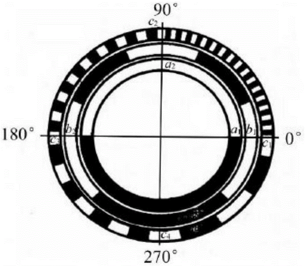
[0026] Such as figure 1 As shown, taking the center point of the matrix code wheel as the coordinate origin, it is divided into four quadrants, and each quadrant is marked with an angle, 0°~90° area, 90°~180° area, 180°~270° area, 270°~360° area The ° areas are the first, second, third, and fourth quadrants, and the four p...

specific Embodiment approach 2

[0051] Embodiment 2. This embodiment is a specific example of Embodiment 1.

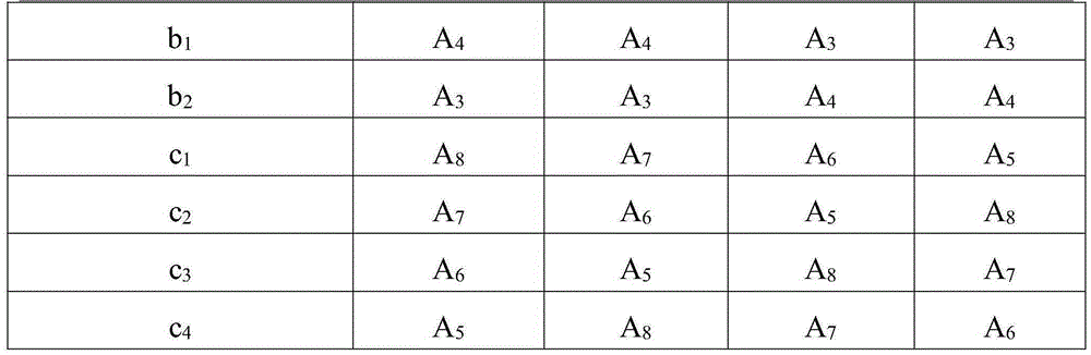
[0052] With the reading head c 1 Take the receiving element of the corresponding photoelectric encoder as an example, as can be seen from Table 1, the reading head c 1 The receiving element at the photoelectric encoder outputs four different groups of photoelectric signals in the four quadrants of the main shaft of the photoelectric encoder: output A in the area of ​​0°~90° 8 , Output A in the area of ​​90°~180° 7 , Output A in the area of ​​180°~270° 6 , Output A in the area of ​​270°~360° 5 . Reading head c 2 The photoelectric signal output state of the receiving element in the four quadrants and the reading head c 1 The receiving elements at the position are only different in order, when the readhead c 1 When the receiving element at the location is damaged, the quadrant position of the main shaft rotation of the photoelectric encoder is judged by the photoelectric signal of the highest two...


PUM


Abstract

The invention relates to the field of encoder optical-electricity signal restoration, in particular to a method for restoring aerospace-grade absolute optical-electricity encoder signals. The problem that an encoder cannot work normally and cannot be manually restored when the aerospace-grade absolute optical-electricity encoder signals are lost is solved. The method comprises the following steps that the relation between all coarse code optical-electricity signals is obtained through an optical-electricity encoder matrix code disc image, when one coarse code optical-electricity signal is lost, the lost coarse code optical-electricity signal is found out through a software program in a debugging system microcontroller, the rest of one or more normally-output optical-electricity signals are used for synthesizing the lost coarse code optical-electricity signal, and the correct optical-electricity encoder position information is obtained by using all the complete optical-electricity signals. The optical-electricity encoder is prevented from outputting wrong position information, the workload is reduced, the work reliability and stability of the optical-electricity encoder are improved, the manual operation is replaced, convenience and fastness are achieved, accuracy is high, and the automatic restoration function of the optical-electricity signals of the optical-electricity encoder is achieved.

Description

technical field [0001] The invention relates to the technical field of encoder photoelectric signal repair, in particular to a method for repairing an aerospace-grade absolute photoelectric encoder signal. Background technique [0002] Light-emitting diodes (LEDs) have long service life, low heat generation, small size, and peak wavelengths that can match photoelectric receiving elements. Therefore, high-precision photoelectric encoders mostly use LEDs as light sources, and photodiodes, phototransistors or photocells as receiving elements. . Because the receiving element is sensitive to temperature, most high-precision photoelectric encoders are used in military projects, industrial sites and special environments. The application environment is very harsh, the temperature difference is large, the change is obvious, the uncertainty of the working environment and the electronic components The long-term use of the device will easily cause damage and aging of the receiving elem...

Claims


Application Information

Patent Timeline
Patent Type & Authority Patents(China)
IPC IPC(8): G01D5/347
Inventor 龙科慧左洋刘金国
Owner CHANGCHUN INST OF OPTICS FINE MECHANICS & PHYSICS CHINESE ACAD OF SCI
Features
  • R&D
  • Intellectual Property
  • Life Sciences
  • Materials
  • Tech Scout
  • Unparalleled Data Quality
  • Higher Quality Content
  • 60% Fewer Hallucinations
Learn More