Image shake correcting apparatus, optical equipment, and imaging device

A shake correction, image technology, applied in the field of image shake correction equipment, to achieve the effect of reducing output fluctuations and suppressing the reduction of driving efficiency

Inactive Publication Date: 2014-05-14
CANON KK
View PDF5 Cites 5 Cited by
  • Summary
  • Abstract
  • Description
  • Claims
  • Application Information

AI Technical Summary

Problems solved by technology

Therefore, in order to extract sufficient driving force even at the lowest output, the voice coil motor has been enlarged accordingly.

Method used


Image

  • Image shake correcting apparatus, optical equipment, and imaging device
  • Image shake correcting apparatus, optical equipment, and imaging device
  • Image shake correcting apparatus, optical equipment, and imaging device

Examples


no. 1 approach )

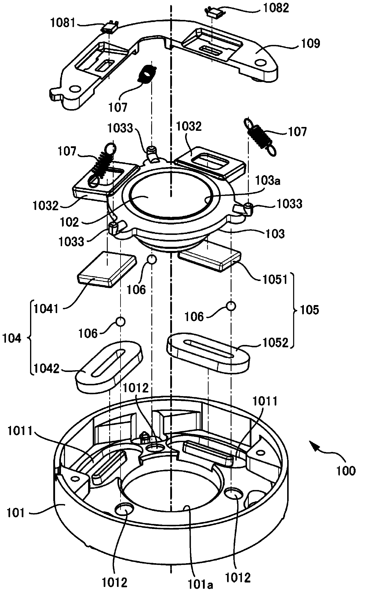
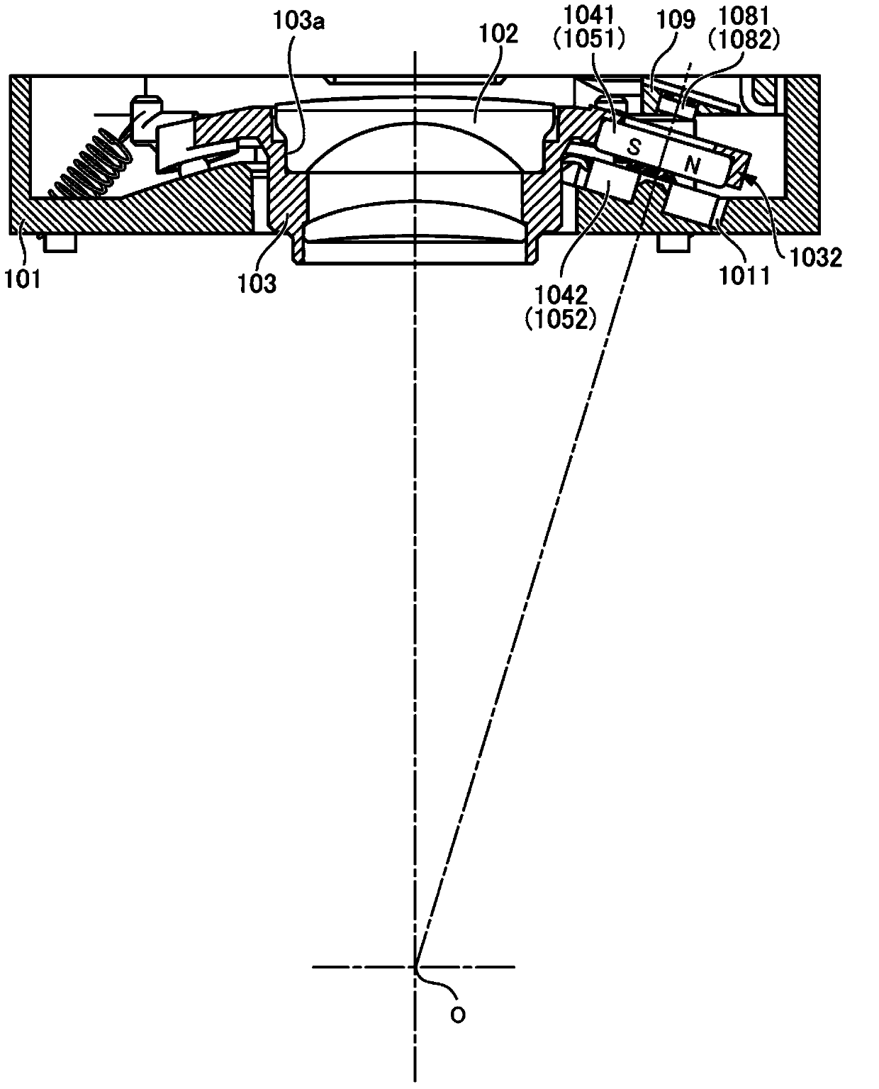
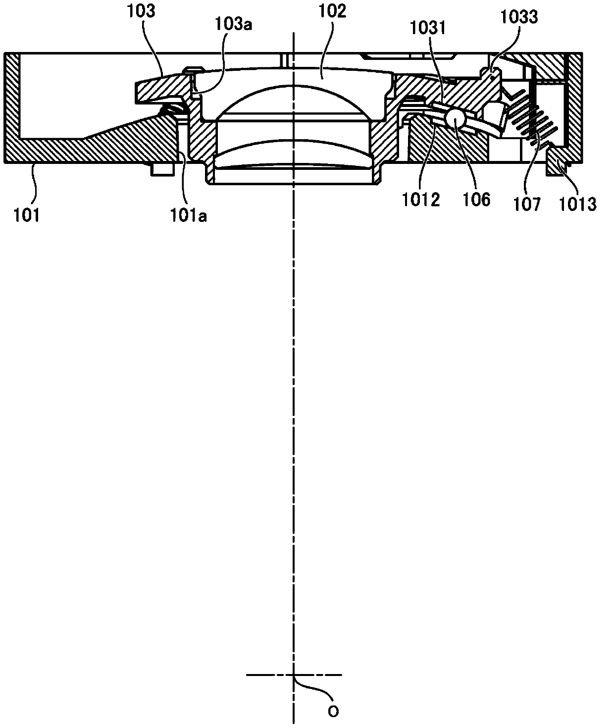
[0033] refer to Figure 1 to Figure 8 An image shake correction device belonging to the first embodiment of the present invention will be described. Figure 1 to Figure 3 is a diagram showing an exemplary configuration of an image shake correction device. figure 1 is an exploded perspective view showing the component configuration of the image shake correction device 100 . figure 2 is a cross-sectional view in a case where the assembled image shake correction device 100 is cut in a plane passing through the rotation center point O and parallel to the first direction (yaw direction). image 3 is a cross-sectional view in a case where the assembled image shake correction device 100 is cut in a plane passing through the rotation center point O and passing through the center of the rolling member (a ball in this embodiment) 106 .

[0034] The image shake correction apparatus 100 has a fixing member 101 and an image shake correction unit 103 holding a correction lens 102 . The ...

no. 2 approach )

[0079] Next, refer to Figure 9 and Figure 10 A second embodiment of the present invention will be described. By using already adopted reference numerals for the same components as those in the first embodiment, detailed description thereof will be omitted, and the description will focus on points different from the first embodiment. This type of abbreviated description is also adopted for other embodiments described below.

[0080] As described above, the output variation of the electromagnetic drive unit can be reduced by reducing the value of the maximum gap change amount Δgmax of the coil and the magnet. As shown in Expression (3) and Expression (4), the gap change amount Δg is determined by the values ​​of Δθ, L, R or R0, and S. Among them, the value of Δθ is determined by the amount of jitter to be suppressed and the optical design. The distance from the rotation center point O to the movable-side opposing surface is approximately equal to the distance from the rota...

no. 3 approach )

[0093] Next, refer to Figure 11 and Figure 12 A third embodiment of the present invention will be described. In the image shake correction apparatus of the third embodiment, the first drive unit 304 is provided with a first magnet 3041 and a first coil 3042 . Figure 11 is a cross-sectional view in a case where the image shake correction device of the present embodiment is cut in a plane passing through the rotation center point O and perpendicular to the rotation axis of the image shake correction unit. Figure 12 is the normal direction of the opposing surface from one movable side (see Figure 11 The figure in the case of observing the image shake correction device of the present embodiment is a straight line (OQ1 direction) indicated by a white arrow in .

[0094] The first magnet 3041 has two planar portions on the opposite surface facing the first coil 3042 . One of the surfaces is designated as the first surface, and the foot of the perpendicular from the rotation...


PUM


Abstract

An image shake correcting apparatus, optical equipment, and an imaging device are disclosed. The image shake correcting apparatus includes a movable member configured to hold an image shake correcting member; a fixed member configured to hold the movable member so as to be movable along a spherical surface centering on a rotational center point; and an electromagnetic drive unit configured to have a magnet and a coil provided in portions that are mutually opposed in the movable member and the fixed member, wherein the magnet and the coil are disposed with inclination from a direction perpendicular to an optical axis so that a direction of drive force that is generated when the coil is energized approximately conforms to a tangential direction of a spherical surface centering on the rotational center point.

Description

technical field [0001] The present invention relates to an image shake correction device included in an image pickup device such as a digital camera or the like, or in an optical device such as an interchangeable lens for a digital single-lens reflex, binoculars, a telescope, or the like. Background technique [0002] An image shake correction device included in a digital camera or the like reduces the time spent on shooting by driving an image shake correction unit holding an optical member or an image pickup element in two directions (yaw direction and pitch direction) on a plane perpendicular to the optical axis. The resulting camera shake effect. The image shake correction device disclosed in Japanese Patent Application Laid-Open No. 2008-134329 prevents optical distortion when the correction lens moves by driving the image shake correction unit holding the correction lens in two directions on a spherical surface centered on a predetermined point. Reduced performance. ...

Claims


Application Information

Patent Timeline
Patent Type & Authority Applications(China)
IPC IPC(8): G03B5/00G02B27/64
CPCG02B27/646
Inventor 安田悠
Owner CANON KK
Why Eureka
Try Eureka