
Single-layer multi-point capacitive touch screen

A capacitive touch screen, single-layer multi-point technology, applied in the direction of electrical digital data processing, instruments, data processing input/output process, etc., can solve problems such as short circuit of lead wires, small distance between welding pads, and low production yield of touch screens. To achieve the effect of improving the production yield rate, improving the production yield rate, and solving the short circuit of adjacent lead wires

Active Publication Date: 2014-05-14
ORISE TECHNOLOGY CO LTD
View PDF5 Cites 13 Cited by
  • Summary
  • Abstract
  • Description
  • Claims
  • Application Information

AI Technical Summary

Problems solved by technology

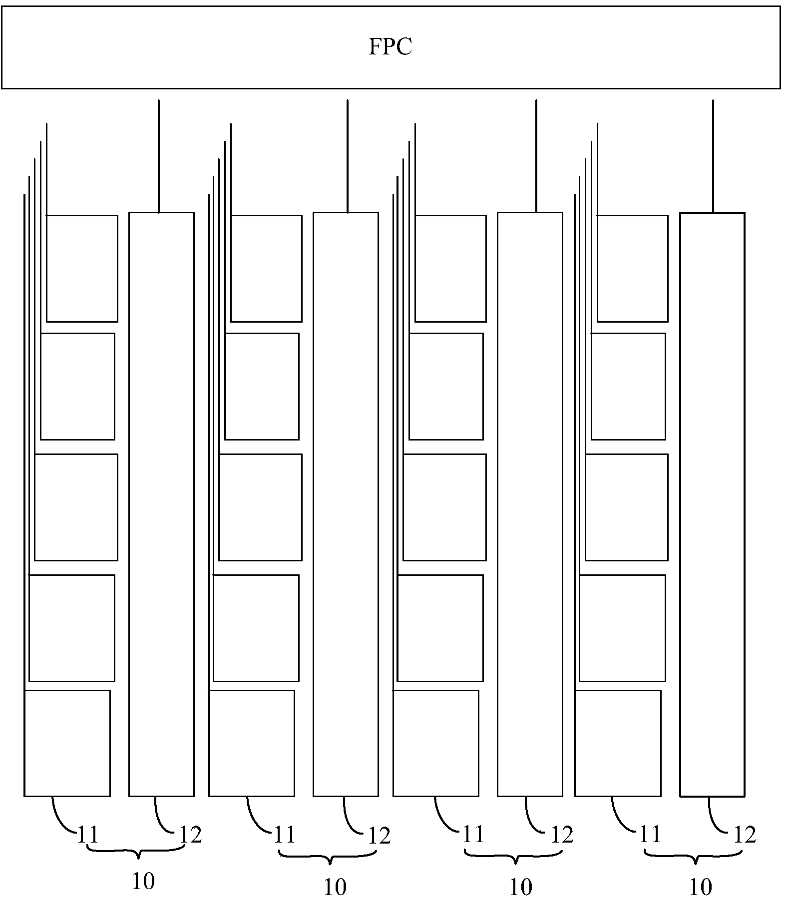
[0006] However, in the existing single-layer multi-point capacitive touch screen, each first electrode 11 needs a lead wire to be connected to the FPC board. Since the number of first electrodes 11 is very large, there are many lead wires drawn from the entire touch screen. The number of corresponding welding pads is also very large (one lead-out line corresponds to one welding pad)
Although the wire-bonding process and the materials used in the wire-bonding process have been strictly controlled, since all the lead-out lines are led out of the touch screen in the same direction, the number of lead-out lines is very large, and the number of corresponding welding pads is large, resulting in the gap between adjacent welding pads. The distance between them is very small. In the wire bonding process, the problem of short circuit of adjacent lead wires will still occur, resulting in low production yield of the touch screen.

Method used


Image

  • Single-layer multi-point capacitive touch screen
  • Single-layer multi-point capacitive touch screen
  • Single-layer multi-point capacitive touch screen

Examples


no. 1 example

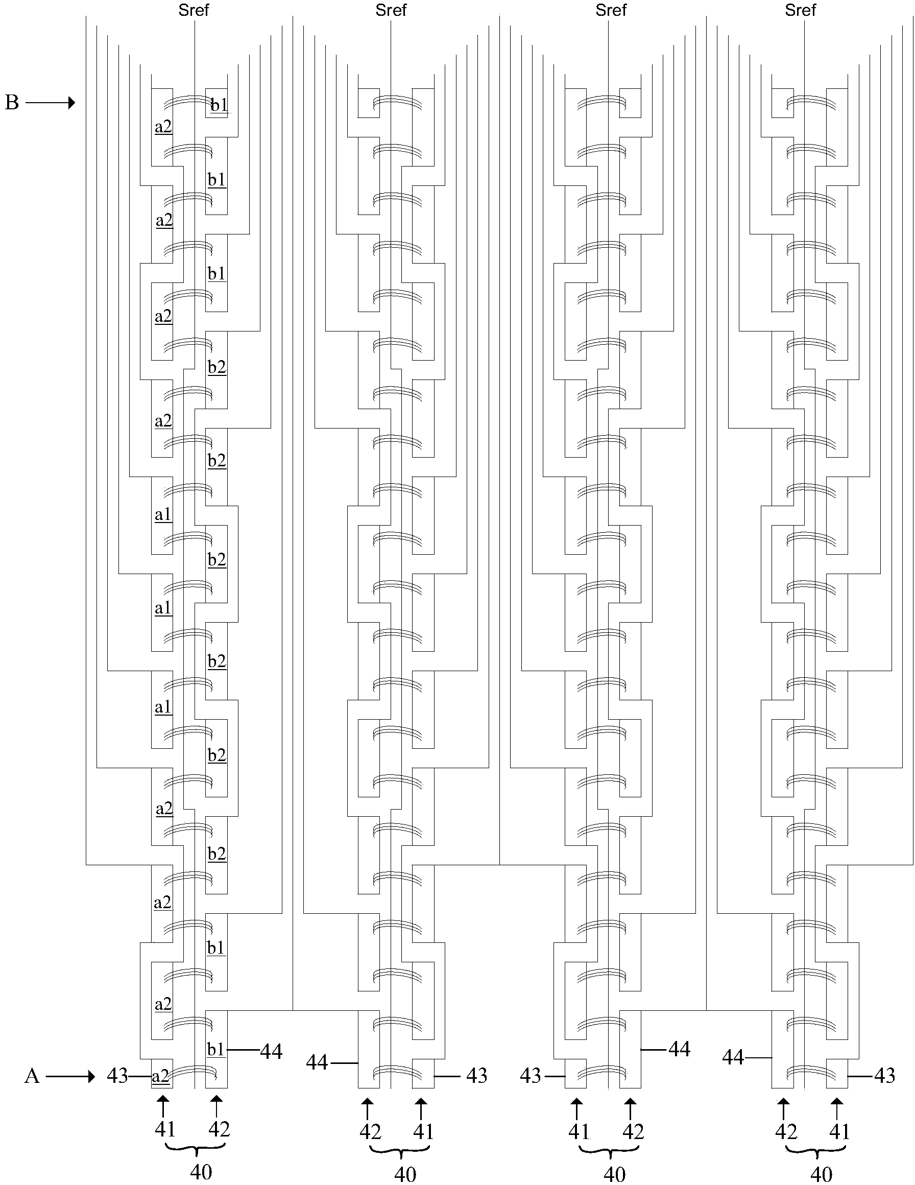
[0056] The following electrode units are arranged side by side, the first electrode group and the second electrode group between the electrode units are arranged side by side, the first electrodes in the first electrode group are arranged in rows, and the electrodes in the second electrode group are arranged in parallel. The second electrodes are arranged in rows. The direction in which the first and second electrodes in each electrode unit are arranged in a column is defined as the first direction, and the direction in which the electrode units are arranged is defined as the second direction, and the second direction is perpendicular to the first direction.

[0057] The term "corresponding" used in the present invention means: along the second direction, the corresponding first electrode and the second electrode have overlapping portions.

[0058] figure 2 It is a schematic diagram of electrode distribution and lead wires of a single-layer multi-point capacitive touch scree...

no. 2 example

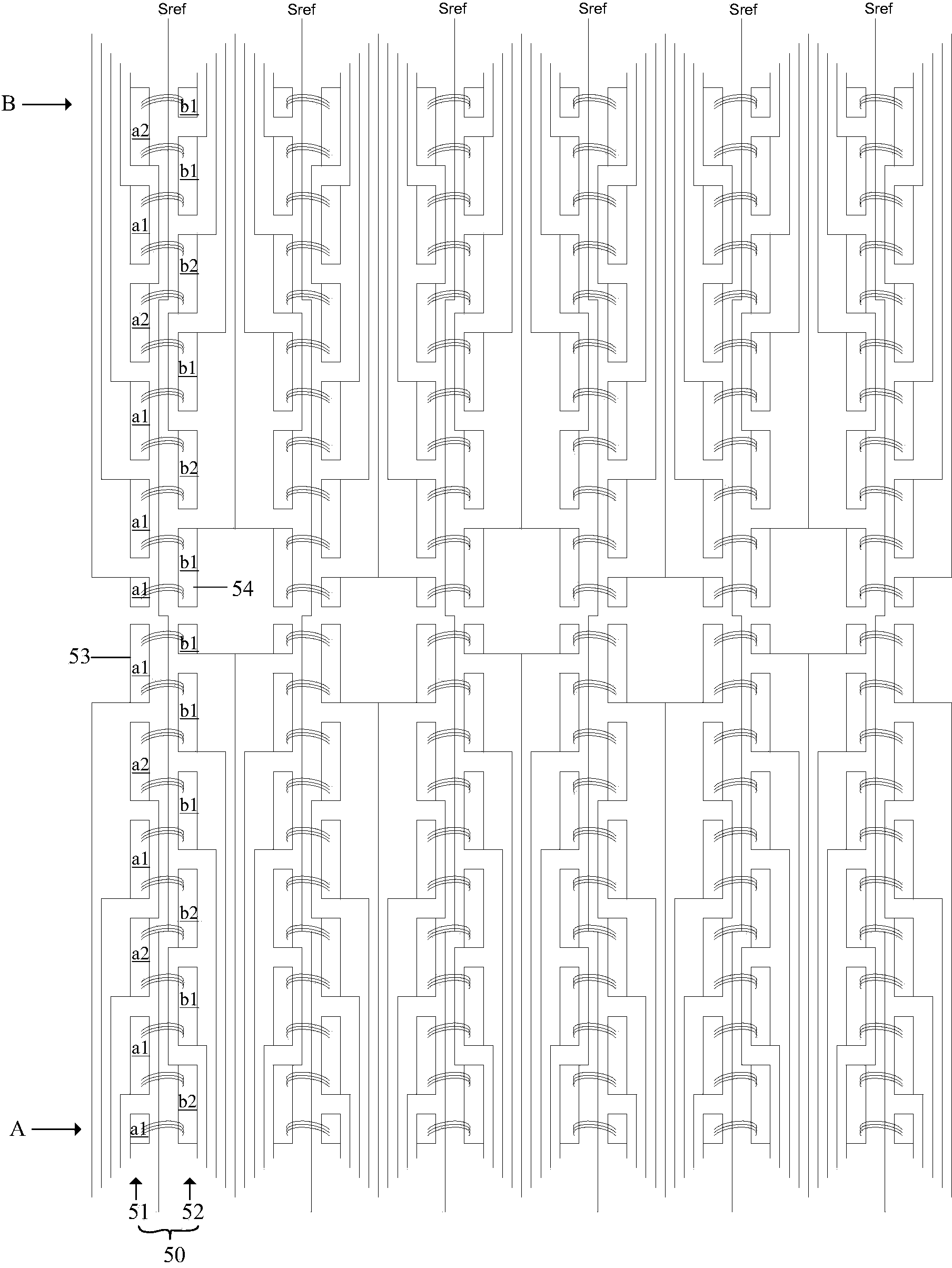
[0083] image 3 It is a schematic diagram of electrode distribution and lead wires of a single-layer multi-point capacitive touch screen in the second embodiment of the present invention, refer to image 3 , the difference between the second embodiment and the first embodiment is:

[0084] The number of electrode units 50; in each electrode unit 50, the numbers of the first electrodes 53 and the second electrodes 54 are 12, which are different from the first embodiment.

[0085] In each electrode unit 50, the corresponding conditions of the first electrode 53 and the second electrode 54 are different:

[0086] In each electrode unit 50, two first electrodes 53 correspond to only one second electrode 54 respectively, and the remaining first electrodes 53 correspond to two second electrodes 54 respectively; the two second electrodes 54 correspond to only one first electrode 53 respectively , the remaining second electrodes 54 correspond to two first electrodes 53 respectively;...

no. 3 example

[0100] Figure 4 It is a schematic diagram of electrode distribution and lead wires of a single-layer multi-point capacitive touch screen in the third embodiment of the present invention, refer to Figure 4 , the difference between the third embodiment and the first embodiment is:

[0101] The number of electrode units 60.

[0102] In each electrode unit 60, the distribution of each first-type first electrode a1, the distribution of each second-type first electrode a2, the distribution of each first-type second electrode b1, and the distribution of each second-type second electrode b2 Unlike the first embodiment:

[0103] In the first electrode group 61, the first electrodes 63 located in the first row and the third row are the first electrodes a2 of the second type, and there is a first electrode a1 of the first type between them; the remaining first electrodes 63 are The first type of first electrode a1.

[0104] In the second electrode group 62, the second electrodes 64 l...


PUM


Abstract

A single-layer multi-point capacitive touch screen comprises multiple electrode units, wherein each electrode unit comprises multiple first electrodes and multiple second electrodes. In at least one electrode unit, each first electrode of at least one part of first electrodes corresponds to at least two second electrodes. The first electrodes and the second electrodes comprise two types of electrodes. The first-type first electrodes and the first-type second electrodes are independent and are not connected. The second-type first electrodes and the second-type second electrodes are respectively connected at least one of the other second-type first electrodes and the other second-type second electrodes, and the second-type first electrodes and the second-type second electrodes which are connected are not adjacent. The connected second-type first electrodes do not correspond to the same-type first electrodes, and the connected second-type second electrodes do not correspond to the same-type first electrodes. In addition, the connected second-type first electrodes and the connected second-type second electrodes are not provided with corresponding portions, or only one of the connected second-type first electrodes is in one-to-one correspondence with one of the connected second-type second electrodes. The touch screen production yield is improved.

Description

technical field [0001] The invention relates to the technical field of touch screens, in particular to a single-layer multi-point capacitive touch screen. Background technique [0002] Touch screen is a kind of touch sensing input device widely used now. According to the principle of touch sensing, touch screens in the prior art include resistive touch screen, capacitive touch screen, surface infrared touch screen and so on. Among them, resistive touch screens are widely used because of their low cost, easy implementation, and simple control; in recent years, capacitive touch screens are characterized by high light transmittance, wear resistance, environmental temperature change resistance, long life, and multi-point touch screens. It is popular with the public for its advanced complex functions. [0003] Among them, the mutual capacitance touch screen is an emerging technology in the capacitive touch screen. It has a good suppression effect on noise and ground parasitic ca...

Claims


Application Information

Patent Timeline
IPC IPC(8): G06F3/044
Inventor 张靖恺郭明
Owner ORISE TECHNOLOGY CO LTD
Learn More