Eureka AIR delivers breakthrough ideas for toughest innovation challenges, trusted by R&D personnel around the world.

A Non-Complementary Flyback Active Clamp Converter

A non-complementary, converter technology, applied in the direction of converting DC power input to DC power output, instruments, and adjusting electrical variables, etc. It can solve the problems that the clamp switch Sa cannot realize soft switching, cannot release energy, and has large turn-on loss. , to achieve the effect of reducing circuit efficiency, increasing on-state loss, and reducing high-frequency oscillation

Active Publication Date: 2016-01-20
MORNSUN GUANGZHOU SCI & TECH
View PDF7 Cites 5 Cited by
  • Summary
  • Abstract
  • Description
  • Claims
  • Application Information

AI Technical Summary

Problems solved by technology

Due to the blocking effect of the fast recovery diode D1, the output capacitor of the clamp switch Sa cannot release energy when the main switch Sw is turned off, and the clamp switch Sa cannot realize soft switching, resulting in a large turn-on loss
Moreover, fast recovery diodes are used, and serious EMI will be generated when high-frequency current flows

Method used


Image

  • A Non-Complementary Flyback Active Clamp Converter
  • A Non-Complementary Flyback Active Clamp Converter
  • A Non-Complementary Flyback Active Clamp Converter

Examples


Embodiment 1

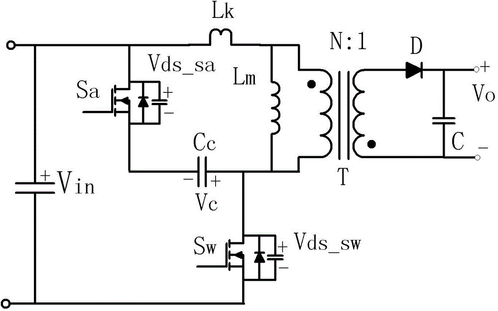
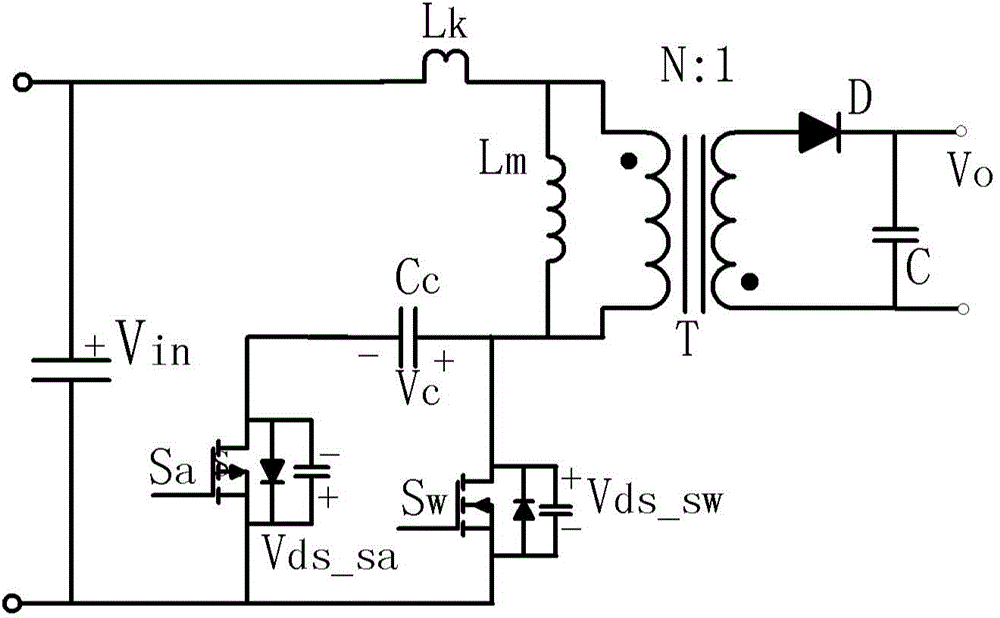
[0046] Such as Figure 7-1 As shown, the non-complementary flyback active clamp converter of Embodiment 1 of the present invention includes a transformer T, a main switch tube Sw, a clamp switch tube Sa, a clamp capacitor Cc, a drive module and an isolated drive circuit. The primary winding and the main switching tube Sw are connected in series for the input voltage signal, the secondary winding of the transformer T is used for outputting the transformed voltage signal, and the clamping switching tube Sa is an NMOS tube, which is connected in series with the clamping capacitor Cc to the transformer The primary windings of T are connected in parallel. The driving module outputs the main driving signal Vgs_sw for controlling the main switching tube Sw to be turned on and off alternately to the driving end of the main switching tube Sw, and the driving module outputs the clamping driving signal Vgs_sa to the driving end of the clamping switching tube Sa, The clamp drive signal V...

Embodiment 2

[0062] Such as Figure 9 As shown, the non-complementary flyback active clamp converter of the second embodiment of the present invention is basically the same as the first embodiment, and their difference is that in the second embodiment, the driving module includes a main control circuit and a second control detection circuit, They can be integrated in one chip.

[0063] see Figure 10 The main control circuit of the second embodiment includes a clock oscillation generator OSC, a second pulse signal module NarrowPulse2 for forming a second pulse signal Vgs_sa2, a second delay circuit Delay2, a logic circuit Logic, a ramp circuit Slope and a drive circuit Drive , the second control detection circuit includes a third delay circuit Delay3 and a first pulse signal module NarrowPulse1; the output terminal of the clock oscillation generator OSC is connected to the input terminal of the second pulse signal module NarrowPulse2, and the other is connected to the second delay The in...


PUM


Abstract

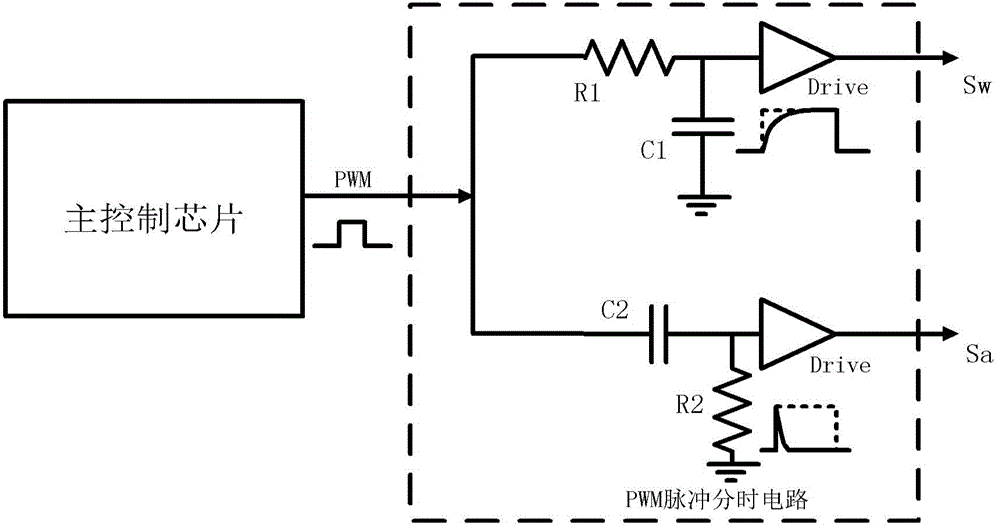
The invention discloses a non-complementary flyback active clamp converter. The non-complementary flyback active clamp converter comprises a transformer, a main switching tube, a clamp switching tube, a clamp capacitor and a drive module. The drive module outputs main drive signals to the drive end of the main switching tube, and the driving signals are used for controlling the main switching tube to be alternately switched on and switched off. The drive module outputs clamp drive signals to the drive end of the clamp switching tube. The clamp drive signals and the main drive signals have the same period. Each period comprises a first pulse signal which is generated when the switching-on state of the main switching tube is converted to the switching-off state, a second pulse signal which is generated when the main switching tube is in the switching-off state, and a signal which is generated at the remaining time and used for controlling the switching-on and the switching-off of the clamp switching tube, wherein the first pulse signal and the second pulse signal are independent of each other and both used for controlling the switching-on and the switching-off of the clamp switching tube. By the adoption of the non-complementary flyback active clamp converter, it is guaranteed that a high-frequency current generated when the clamp capacitor is charged fully flows through the clamp switching tube and avoids a backward diode of the clamp switching tube.

Description

technical field [0001] The invention relates to a switch power converter, in particular to a non-complementary flyback active clamp converter. Background technique [0002] With the rapid development of the field of power electronics, switching converters are used more and more widely, especially people put forward more requirements for switching converters with high power density, high reliability and small size. Generally, the traditional low-power AC / DC conversion is realized by the flyback topology, which has the advantages of simple structure and low cost; however, due to the influence of the leakage inductance of the transformer, the voltage clamping method of the main switching tube of the flyback converter includes RC buffer absorption , RCD clamp, LCD clamp and active clamp. The active clamp can not only absorb the energy of the leakage inductance and feed it back to the output terminal in the form of forward excitation, but also can make full use of the energy of ...

Claims


Application Information

Patent Timeline
Patent Type & Authority Patents(China)
IPC IPC(8): H02M3/335
Inventor 黄天华张少维
Owner MORNSUN GUANGZHOU SCI & TECH
Why Eureka
Eureka Blog
Learn More