
Shooting optimization device, image-pickup device and shooting optimization method

A technology of camera device and optimization device, which is applied in the field of shooting optimization device, camera device, and shooting optimization, which can solve insurmountable problems and achieve the effects of reducing zoom, clear shooting, and prolonging the life of the lens

Inactive Publication Date: 2014-05-14
HITACHI LTD
View PDF5 Cites 23 Cited by
  • Summary
  • Abstract
  • Description
  • Claims
  • Application Information

AI Technical Summary

Problems solved by technology

However, in the prior art represented by Comparative Document 1, no effective solution is proposed to the above technical problems, and the above obstacles cannot be overcome.

Method used


Image

  • Shooting optimization device, image-pickup device and shooting optimization method
  • Shooting optimization device, image-pickup device and shooting optimization method
  • Shooting optimization device, image-pickup device and shooting optimization method

Examples


no. 1 approach )

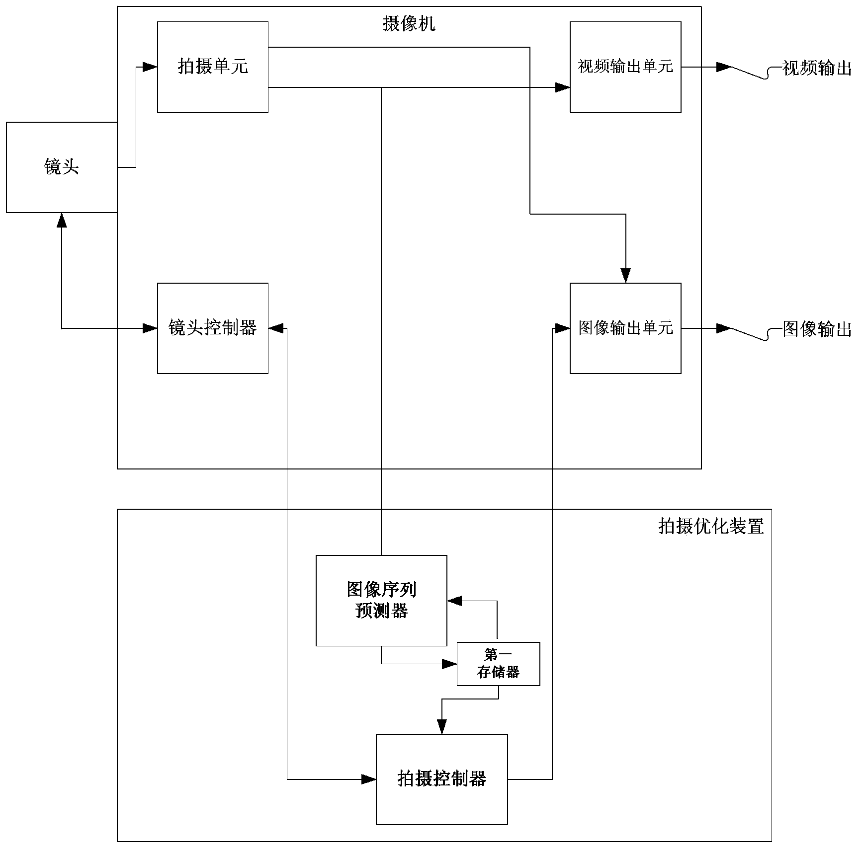
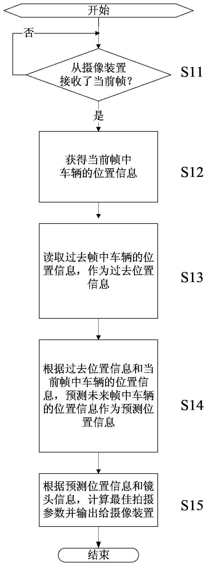
[0058] First, combine figure 2 , image 3 , Figure 4 and Figure 5 The imaging optimization device and imaging optimization method according to the first embodiment of the present invention will be described. in, figure 2 A schematic structural block diagram showing an image capture optimization device according to the first embodiment of the present invention, image 3 , Figure 4 and Figure 5 The method steps of the shooting optimization method of the first embodiment of the present invention are shown in a flow chart.

[0059] Such as figure 2 As shown, the shooting optimization device according to the first embodiment of the present invention includes an image sequence predictor, a first memory and a shooting controller. The shooting optimization device is capable of data communication with the surveillance camera, for example, via a wired connection or wireless transmission. The video camera has a zoom lens, and also includes a shooting unit, a lens controll...

no. 2 approach )

[0134] Figure 13 A schematic structural block diagram of an imaging device according to a second embodiment of the present invention is shown. Such as Figure 13 As shown, the imaging device of the second embodiment is constructed by incorporating the shooting optimization device of the first embodiment into the camera. Each structure of the imaging device is the same as that described in the first embodiment, and will not be repeated here.

[0135] According to the imaging device of the second embodiment, it is obvious that the same technical effect as that of the first embodiment can be obtained. Furthermore, various preferred forms and modified examples of the first embodiment can also be applied to the imaging device of the second embodiment, and corresponding effects can be obtained.


PUM


Abstract

The invention provides a shooting optimization device, an image-pickup device and a shooting optimization method which can make road traffic monitored. The shooting optimization device controls the image-pickup device which is used for road traffic monitoring and is provided with a zoom lens; the shooting optimization device comprises an image sequence predictor, a first memory and a shooting controller. The shooting optimization method comprise the following steps that: prediction position information of a vehicle in a future image is predicted according to a historic position information of the vehicle in a photographed image and position information of the vehicle in a current image; and an optimal shooting parameters of the image-pickup device are calculated according to the prediction position information and the lens information of the zoom lens. With the shooting optimization device and the shooting optimization method adopted, the optimal shooting parameters of the image-pickup device which is provided with the zoom lens can be pre-determined, and the complete focal length of a zoom camera can be fully utilized to cover a distance range as wide as possible, such that clear shooting can be realized, and the shooting of a blank image and missed shooting of high-speed vehicles can be avoided; and the frequency of zooming and focusing, and action time of the zoom lens can be decreased, and the service life of the lens can be prolonged.

Description

technical field [0001] The invention relates to the field of road traffic monitoring, in particular to a shooting optimization device, a camera device and a shooting optimization method for optimizing image shooting of road traffic monitoring. Background technique [0002] In the field of road traffic monitoring, road monitoring cameras can be divided into two types: fixed focus and zoom. [0003] Traditional road surveillance cameras are all fixed focus, and most of them are fixed focus. Even with a zoom lens, its focal length and focus are mostly unchanged without human control. [0004] In recent years, road surveillance cameras using zoom lenses have gradually begun. Zoom is to change the focal length (zoom) is to change the range of field of view, the longer the focal length, the smaller the real object area covered by the screen. In addition, focusing means changing the focus (focal) is to change the distance between the clear imaging part of the field of view and t...

Claims


Application Information

Patent Timeline
IPC IPC(8): H04N5/232G08G1/01
Inventor 吕越峰王瑾娟
Owner HITACHI LTD
Learn More