Illumination moudle for creating lateral rectangular illumination window

a technology of illumination window and illumination module, which is applied in the direction of lighting and heating apparatus, semiconductor devices for light sources, instruments, etc., can solve the problems of poor lighting at night time, unclear shooting position on the peripheral of the target object, and the aspect ratio of the illumination device cannot meet the standard 4:3 aspect ratio of imaging apparatus or the standard 16:9 aspect ratio of high definition tv (hdtv). achieve the effect of without substantial light loss

Inactive Publication Date: 2017-06-22
LIGITEK ELECTRONICS
View PDF3 Cites 4 Cited by
  • Summary
  • Abstract
  • Description
  • Claims
  • Application Information

AI Technical Summary

Benefits of technology

[0010]For the purposes of adjustment of light projection angle and illumination pattern. The object of the instant disclosure is to provide an efficient illumination module for creating lateral rectangular illumination window without substantial light losses, and can be miniaturized.

Problems solved by technology

However, a common problem of the surveillance cameras is poor lighting at night time.
This may result in an unclear shooting position on the peripheral of the target object.
In addition, the light illumination range, window, and aspect ratio of the illumination device cannot meet the standard 4:3 aspect ratio of imaging apparatus or the standard 16:9 aspect ratio of high definition TV (HDTV).
Thus, there is always some distortion of the captured image of the target object.
However, during the compression process, there may be compression artifacts generated anywhere of the image frame.

Method used


Image

  • Illumination moudle for creating lateral rectangular illumination window
  • Illumination moudle for creating lateral rectangular illumination window
  • Illumination moudle for creating lateral rectangular illumination window

Examples


first embodiment

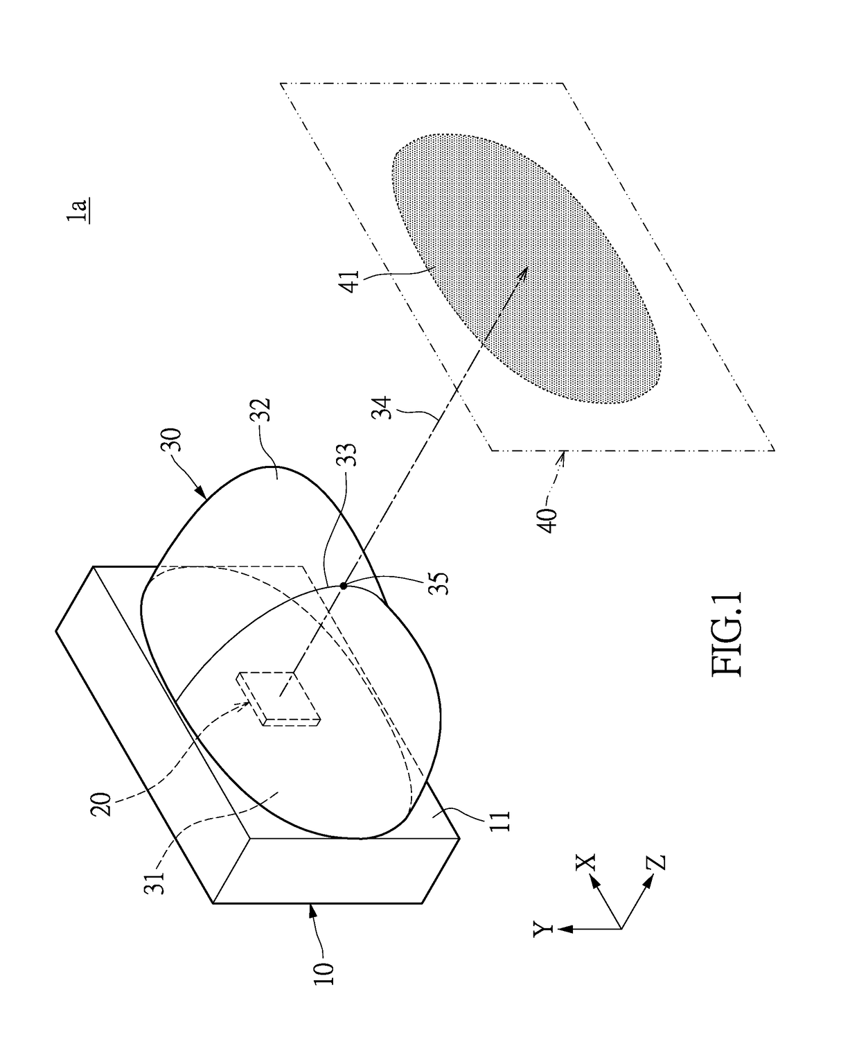
[0032]Please refer to FIG. 1. This is a perspective diagram showing an illumination module for creating lateral rectangular illumination window according to a first embodiment of the present invention. The illumination module 1a includes a substrate 10, a light-emitting element 20, and an optical lens 30.

[0033]The substrate 10 includes an installation surface 11 for arrangement of the light-emitting element 20. For the instant embodiment, the substrate 10 can be but not limited to a metal substrate, a ceramic substrate, or a glass fiber substrate (e.g., FR-4, FR-5, G-10, and G-11). Specifically, the metal substrate is made of copper, copper alloy, aluminum, aluminum alloy, magnesium alloy, aluminum silicon carbide, or carbon composition. The ceramic substrate is made of aluminum oxide, aluminum nitride, zirconium oxide, silicon carbide, hexagonal boron nitride, or fluorinated carbon. Preferably, on a surface opposite to the installation surface 11 of the substrate 10 there can be ar...

second embodiment

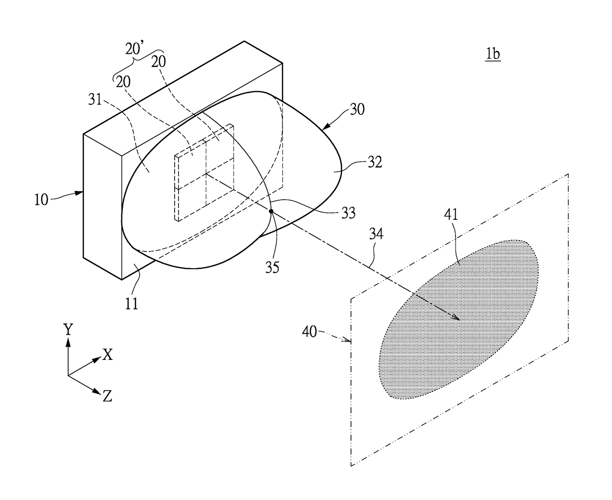
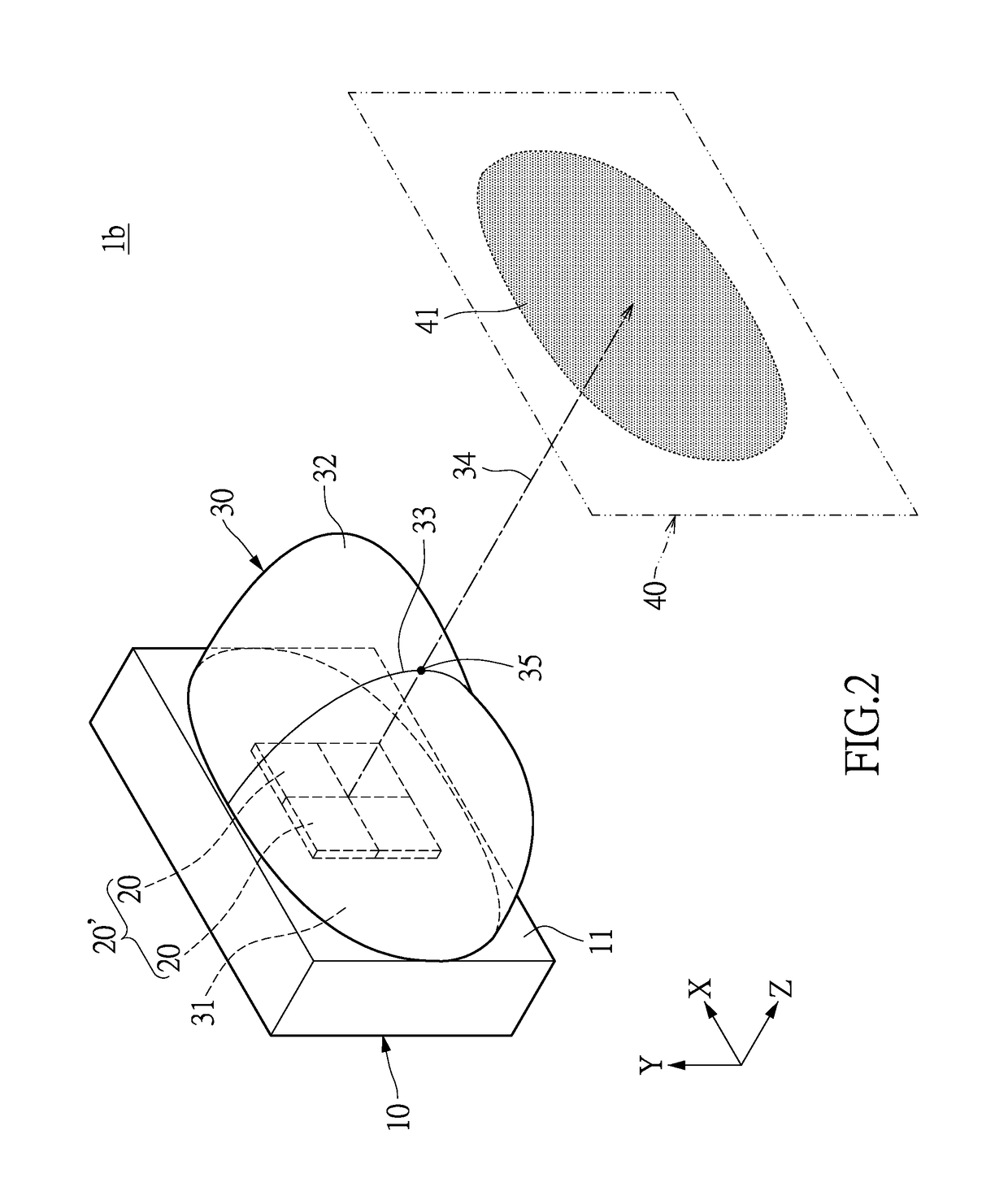
[0039]Please refer to FIG. 2. This is a perspective diagram showing an illumination module for creating lateral rectangular illumination window according to a second embodiment of the present invention. The illumination module 1b includes a substrate 10, a plurality of light-emitting elements 20, and an optical lens 30. Compared with the first embodiment, the light-emitting elements 20 are arranged in a non-rectangular array 20′. For example, the illumination module 1b, as shown in FIG. 2, includes four light-emitting elements 20 arranged in a square array 20′, of which each two light-emitting elements 20 are in a row.

[0040]Please note that the square array 20′ shown in FIG. 2 consists of four light-emitting elements 20, but embodiments are not limited to any particular number of light-emitting elements 20. In various embodiments, the square array 20′ may consist of nine light-emitting elements 20, and each three light-emitting elements 20 are in a row.

[0041]The substrate 10 include...


PUM


Abstract

Disclosed is an illumination module for creating lateral rectangular illumination window which includes a substrate, at least one light-emitting element, and an optical lens. The light-emitting element is mounted on the substrate for generating visible light or invisible light, and having an optical axis. The optical lens is arranged on the substrate to cover the light-emitting element. The optical lens includes a light-entrance surface and a light-exiting surface opposite to the entrance surface, and the light-exiting surface has a light emission center. The light-exiting surface of the optical lens can be configured to direct a beam of light generated by the light-emitting element to output along the optical axis and pass through the light emission center to create a lateral rectangular illumination window. Whereby, the components of a camera can be reduced, and image distortion caused by compressing and converting can be prevented.

Description

BACKGROUND OF THE INVENTION[0001]1. Field of the Invention[0002]The instant disclosure relates to an illumination module, in particular, to an illumination module for creating lateral rectangular illumination window.[0003]2. Description of Related Art[0004]Nowadays, surveillance cameras are very widely used in places such as factories, dormitories, stores, buildings, and gateways of community housings, or secret areas, to monitor human activities and save information under visible light or invisible light conditions for the uses of trace and authentication. Thereby, those who having bad intentions will be threaten and warned against the illegal acts, and thus the public can be ensured from crimes.[0005]In the surveillance cameras there is arranged at least one LED (Light Emitting Diode) or laser illumination device to assist image capture. Thus, the surveillance cameras can start monitoring under poor lighting conditions. In general, the illumination device can generate an infrared ...

Claims


Application Information

Patent Timeline
Patent Type & Authority Applications(United States)
IPC IPC(8): F21V5/04
CPCF21V5/04F21Y2115/30F21Y2115/10G02B19/0014G02B19/0061G02B19/0066G03B15/03G03B2215/0567G03B2215/0592
Inventor LEE, HSIAO-WENTUNG, I-HSIN
Owner LIGITEK ELECTRONICS
Why Eureka
Try Eureka