Heat radiation module and electronic device

A heat dissipation module and electronic device technology, applied in the direction of cooling/ventilation/heating transformation, etc., can solve problems such as poor heat dissipation of heat sources, and achieve the effect of reducing the probability of poor heat dissipation

Active Publication Date: 2014-05-14
INVENTEC PUDONG TECH CORPOARTION +1
View PDF15 Cites 17 Cited by
  • Summary
  • Abstract
  • Description
  • Claims
  • Application Information

AI Technical Summary

Problems solved by technology

[0004] However, if multiple heat sources are included in the electronic device, since these heat sources are at different distances from the fan, the airflow blown from the fan passes through the cooling fins of the closer heat source, and then flows through another group of heat radiation fins behind this group. One set of cooling fins often leads to poor heat dissipation of the heat source contacted by the other set of cooling fins

Method used


Image

  • Heat radiation module and electronic device
  • Heat radiation module and electronic device

Examples


Embodiment Construction

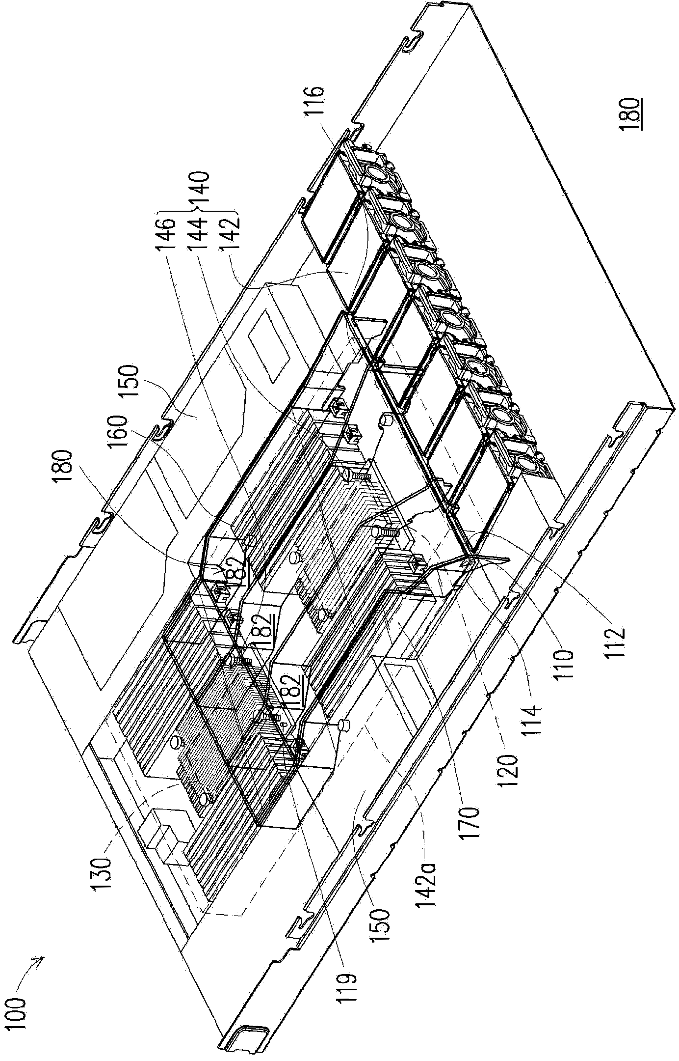
[0047] figure 1 is a schematic diagram of an electronic device according to an embodiment of the present invention. see figure 1 , in order to show the internal configuration of the electronic device 100 more clearly, in figure 1 , the upper cover of the electronic device 100 is hidden. The electronic device 100 of this embodiment includes a motherboard 110 , a first heat source 120 , a second heat source 130 and a heat dissipation module 140 . The first heat source 120 and the second heat source 130 are respectively disposed on the motherboard 110 . In this embodiment, the first heat source 120 and the second heat source 130 are central processing units, but in other embodiments, the first heat source 120 and the second heat source 130 can also be other heating elements.

[0048] In addition, in this embodiment, a plurality of memory modules are disposed on both sides of the first heat source 120 and the second heat source 130 respectively. Since the memory modules also e...


PUM


Abstract

The invention relates to an electronic device. The electronic device comprises a mainboard, a first heat source, a second heat source and a heat radiation module. The first heat source and the second heat source are arranged on the mainboard. The heat radiation module comprises at least one fan, a first heat radiation module and a second heat radiation module. The fan is arranged at a first side of the mainboard, air flow blown from the fan flows along a flow path. The first heat radiation module comprises a first board body in thermal contact with the first heat source and a plurality of first heat radiation fins. The second heat radiation module comprises a second board body in thermal contact with the second heat source and a plurality of second heat radiation fins. The first heat radiation module and the second heat radiation module are located inside the flow path, air flow generated by the fan flows along the flow path firstly through the first heat radiation module and then through the second heat radiation module, and an interval between the first heat radiation fins is larger than that between the second heat radiation fins.

Description

technical field [0001] The invention relates to a cooling module and an electronic device. Background technique [0002] As the integration and thermal power of internal components of integrated circuit (Integrated Circuit, IC) chips continue to increase, the heat dissipation performance of the heat dissipation system of the IC chip must also be relatively improved. Generally speaking, electronic components with IC chips, such as the central processing unit, graphics chips, and chipsets of personal computers, will generate heat energy during high-speed operation, thereby increasing the temperature of the electronic components themselves. Therefore, in order to allow the IC chips of electronic components to maintain long-term normal operation under high-speed operation, the heat energy generated by the IC chips of these electronic components must be removed quickly to reduce the excessive temperature of the IC chips. Otherwise, once the temperature of the IC chip exceeds the...

Claims


Application Information

Patent Timeline
Patent Type & Authority Applications(China)
IPC IPC(8): H05K7/20
Inventor 张贵姣
Owner INVENTEC PUDONG TECH CORPOARTION
Why Eureka
Try Eureka