Component mounting device and component mounting method

A technology for installing equipment and components, applied in the field of component installation equipment and component installation, can solve the problems of heavy work load, difficult installation work for operators, and heavy work load for operators, so as to improve production efficiency, reduce work burden, and achieve efficient installation. effect of work

Inactive Publication Date: 2016-04-20
HONDA MOTOR CO LTD
View PDF7 Cites 0 Cited by
  • Summary
  • Abstract
  • Description
  • Claims
  • Application Information

AI Technical Summary

Problems solved by technology

[0008] However, in the component mounting equipment disclosed in Patent Document 1, when the number of components to be mounted on the workpiece is large, the number of man-hours for the operator to grasp increases, and the workload on the operator becomes excessive.
In addition, since the workload on the operator becomes excessive, it is difficult for the operator to perform the installation work efficiently.

Method used


Image

  • Component mounting device and component mounting method
  • Component mounting device and component mounting method
  • Component mounting device and component mounting method

Examples


Embodiment

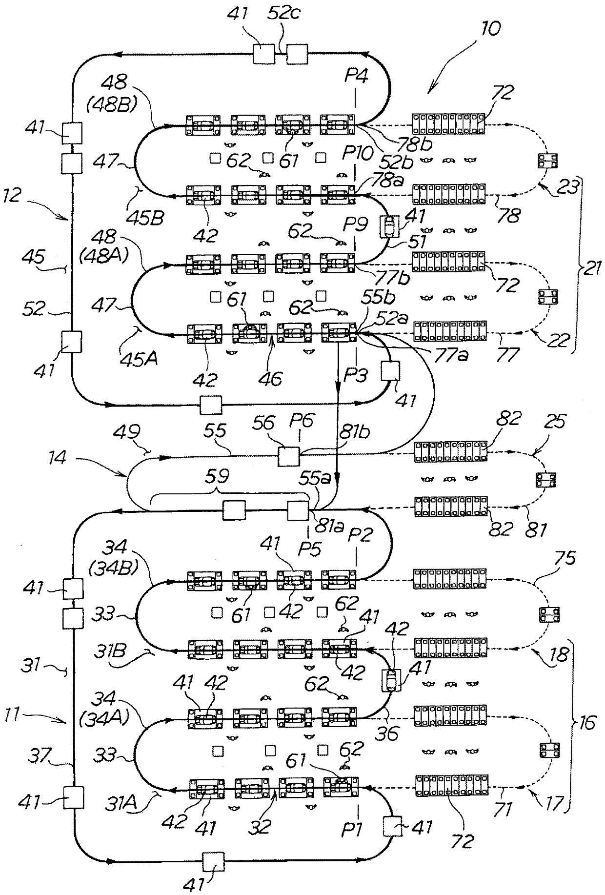
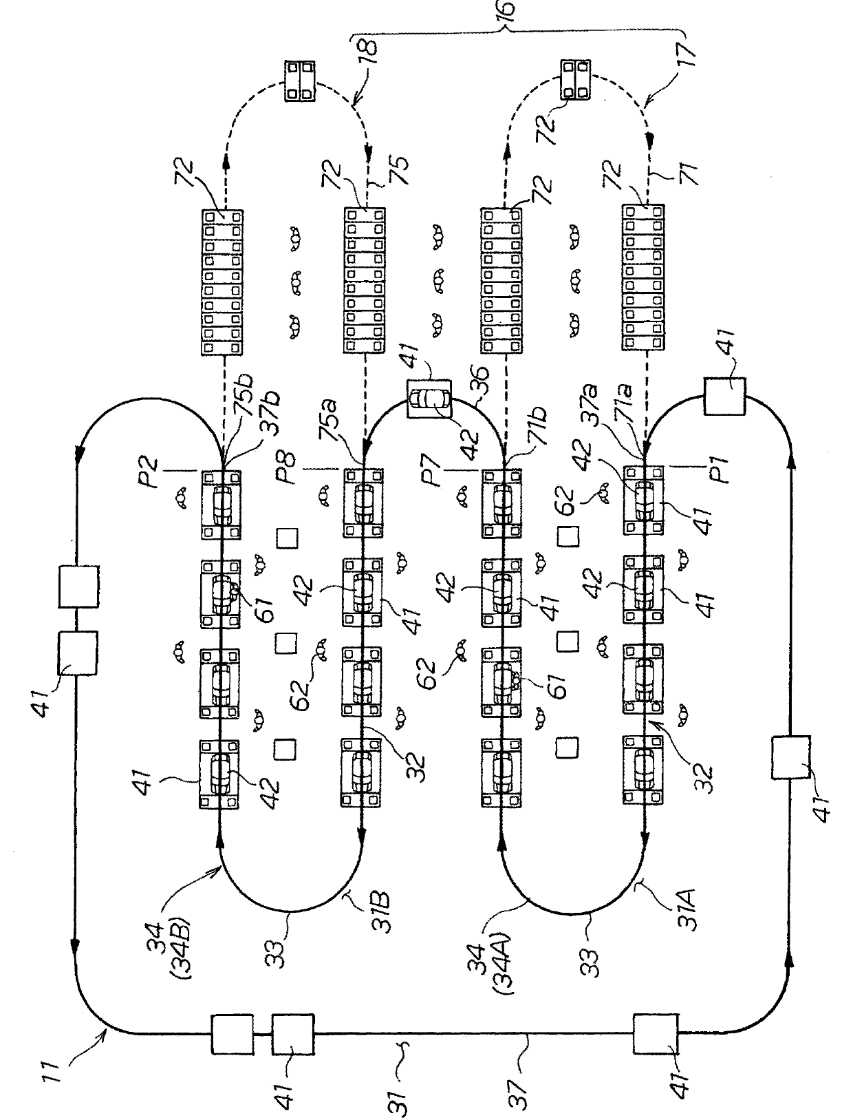
[0042] Although one or more operators 61 may be loaded on the workpiece transfer trolley 41 depending on the type of workpiece 42, in figure 1 , figure 2 In FIG. 2 , for ease of understanding, it is shown that one worker 61 is mounted on the work conveyance cart 41 . In addition, although the operator 61 is mounted on each workpiece transport trolley 41, the figure 1 , figure 2 A state in which an operator 61 is mounted on the selected workpiece transport cart 41 is shown in .

[0043] refer to figure 1 , the component mounting facility 10 includes: a first component mounting facility 11 provided on the upstream side, a second component mounting facility 12 provided on the downstream side of the first component mounting facility 11, a second component mounting facility 12 provided at the first component mounting facility 11 and a second component The lifting and conveying mechanism 14 between the installation equipment 12 is installed.

[0044] In addition, the componen...


PUM


Abstract

The invention provides a component mounting device and a component mounting method. The parts mounting equipment (10) is provided with a plurality of turning parts (33, 47) on the transport path (32, 46) in the parts mounting work area (31, 45), thereby providing a plurality of substantially U-shaped parts with turning parts shaped transport paths (34, 48). By connecting the above-mentioned substantially U-shaped conveyance paths respectively, and connecting the substantially U-shaped conveyance paths ( 34A, 48A) on the most upstream side and the most downstream side among the plurality of substantially U-shaped conveyance paths The substantially U-shaped conveyance paths (34B, 48B) are connected together, whereby the workpiece conveyance trolley (41) can be circulated along the conveyance path.

Description

technical field [0001] The present invention relates to a component mounting device and a component mounting method for moving a workpiece conveyance cart along a conveyance path and mounting a component to a workpiece placed on the workpiece conveyance cart. Background technique [0002] In component mounting equipment, for example, the technology disclosed in Patent Document 1 is known: its implementation is performed by specific (one or more) workers during one cycle to complete one assembly or product (hereinafter, referred to as a workpiece) The technology of the assembly method (unit production method). According to this component mounting apparatus, when one workpiece moves in one cycle, a specific worker moves along with the workpiece, and the specific worker can complete the mounting work on the workpiece while the workpiece moves in one cycle. [0003] prior art literature [0004] patent documents [0005] Patent Document 1: Japanese Unexamined Patent Publicati...

Claims


Application Information

Patent Timeline
Patent Type & Authority Patents(China)
IPC IPC(8): B23P21/00B23P19/00B25H1/08B62D65/12
CPCB62D65/10B62D65/12B62D65/18B65G17/20B65G17/32
Inventor 小佐佐伸大堤田胜由高桥秀俊桥本大辅杉本智博佐野浩一
Owner HONDA MOTOR CO LTD
Why Eureka
Try Eureka