Light-transmitting equipment and annealing equipment having said light-transmitting equipment

A technology of annealing equipment and equipment, applied in laser welding equipment, welding equipment, metal processing equipment and other directions, can solve problems such as breakage of transmission windows, and achieve the effects of preventing breakage, saving costs, and increasing replacement cycles.

Active Publication Date: 2016-08-17
AP SYST INC +1
View PDF7 Cites 0 Cited by
  • Summary
  • Abstract
  • Description
  • Claims
  • Application Information

AI Technical Summary

Problems solved by technology

That is, due to the clamping force of the bolt, the frame applies a pressure excessively higher than the tightening strength to the transmission window, thereby causing breakage of the transmission window in the corresponding area

Method used


Image

  • Light-transmitting equipment and annealing equipment having said light-transmitting equipment
  • Light-transmitting equipment and annealing equipment having said light-transmitting equipment
  • Light-transmitting equipment and annealing equipment having said light-transmitting equipment

Examples


Embodiment Construction

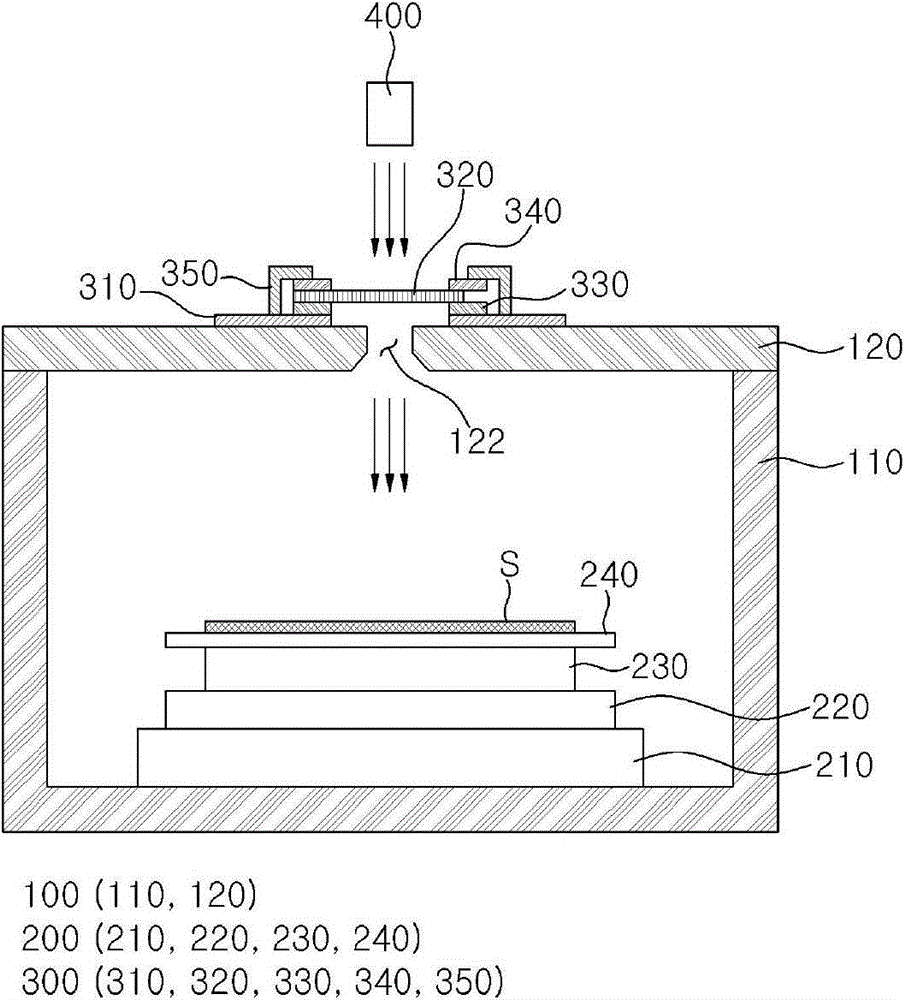
[0050] Now, embodiments according to the present invention will be described in detail with reference to the accompanying drawings. However, the present invention is not limited to the embodiments described below, but it can be embodied in various configurations. This embodiment is provided for sufficient understanding of the present invention, and the scope of the present invention can be fully understood by those of ordinary skill in the art by referring to this embodiment. In the drawings, like numerals indicate like elements.

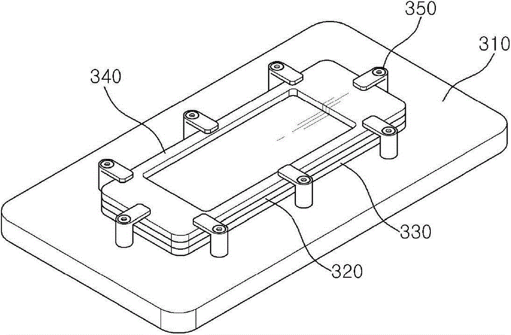
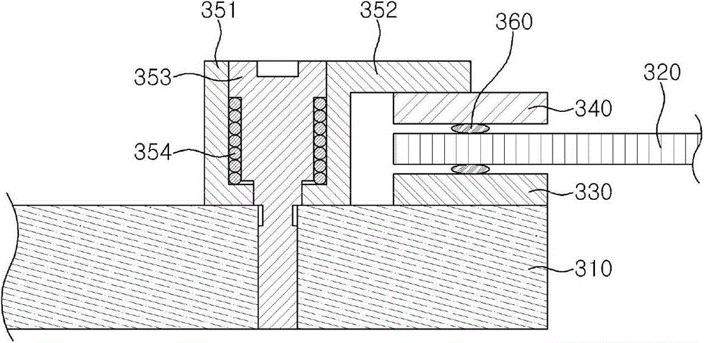
[0051] figure 1 is a schematic diagram showing a laser annealing device according to an embodiment of the present invention. and, figure 2 To show a schematic perspective view of a light-transmitting unit according to an embodiment of the present invention, image 3 is a partial cross-sectional view showing the light-transmitting unit, and Figure 4 is an exploded perspective view showing the light transmission unit with detached clamps. Fig...


PUM


Abstract

The invention provides a light penetration apparatus and an annealing apparatus having the same. The light penetration apparatus includes a light-penetration transmission window, a frame arranged at the edge of the transmission window, and a plurality of clamps for supplying pressure to the frame to tightly fix the transmission window, wherein each clamp includes a body, an elastic part inserted into the body, and a fastening part penetrating through the body via the elastic part and protruding from the lower end of the body, and the elastic part controls the pressed applied by the fastening part in a required range.

Description

technical field [0001] The invention relates to an annealing device. More particularly, it relates to a light penetration device and an annealing device having the same, in which a transmission window through which a laser beam can penetrate can be fixed without damage. Background technique [0002] Thin film transistors (TFTs) are used as circuits for independently driving each of pixels in a display device such as a liquid crystal display (LCD) or organic electroluminescence (EL). The thin film transistor includes a gate electrode, an active layer, a source electrode and a gate insulating film. [0003] In this thin film transistor, the active layer acts as a channel between the gate electrode and the source / drain electrodes. Amorphous or crystalline silicon has been used to form this active layer. However, amorphous silicon has many limitations in manufacturing large-screen liquid crystal displays because amorphous silicon has low electron mobility. Therefore, recent ...

Claims


Application Information

Patent Timeline
Patent Type & Authority Patents(China)
IPC IPC(8): B23K26/00B23K26/08H01L21/324
CPCH01L21/268H01L21/67115H01L21/68714H01L21/02675H01L21/2026H01L27/1285
Inventor 梁相熙李基雄权五成金圣进
Owner AP SYST INC
Why Eureka
Try Eureka