Fluidization system of powder material transport vehicle and powder material transport vehicle

A technology of fluidization system and transportation vehicle, which is applied in the field of fluidization system and powder material transportation vehicle, and can solve the problems of increasing steel usage and welding workload, cracking of sliding plate steel or welding seam, and reducing the effective volume of the tank, etc. Achieve the effects of reducing welding workload, increasing tank volume, and reducing steel usage

Active Publication Date: 2018-11-27
CHINA INTERNATIONAL MARINE CONTAINERS (GROUP) CO LTD +2
View PDF6 Cites 0 Cited by
  • Summary
  • Abstract
  • Description
  • Claims
  • Application Information

AI Technical Summary

Problems solved by technology

The production of the fluidized system with these structures is relatively complicated, and the existence of the side sliding sheet and the triangular sliding sheet increases the amount of steel used and the workload of welding, while increasing the cost and reducing the effective volume of the tank
In addition, because the fluidization system adopts the pneumatic unloading method, the tank needs to bear the air pressure, and the flat sliding plate has poor pressure bearing capacity, so a pressure balance structure is required. If the structure is not handled properly, it is easy to cause the steel or weld of the sliding plate to crack

Method used


Image

  • Fluidization system of powder material transport vehicle and powder material transport vehicle
  • Fluidization system of powder material transport vehicle and powder material transport vehicle
  • Fluidization system of powder material transport vehicle and powder material transport vehicle

Examples


Embodiment Construction

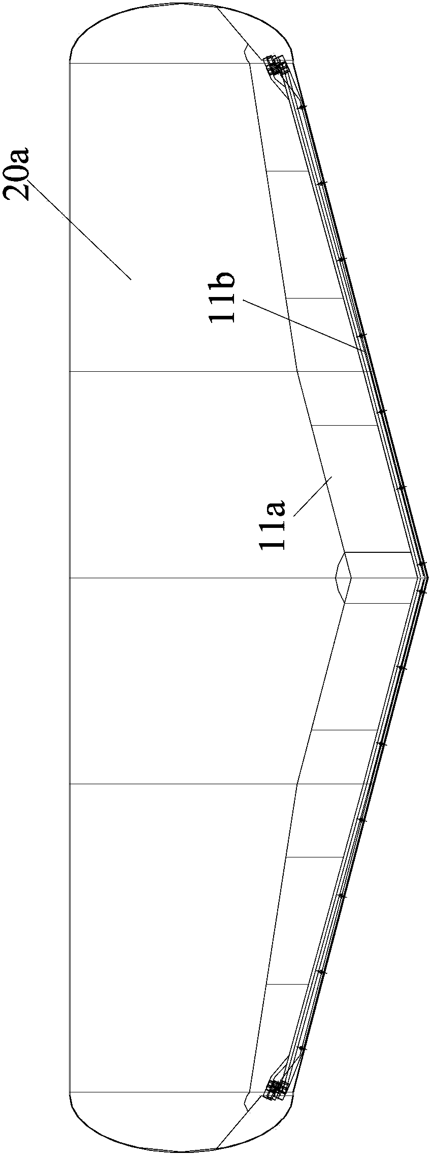
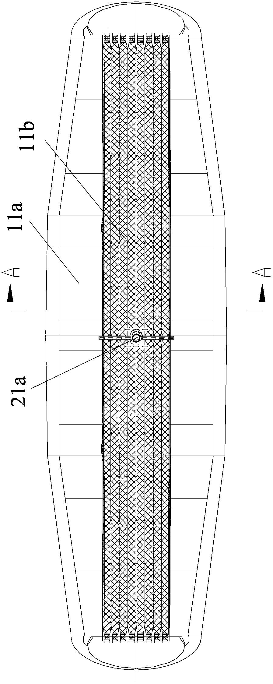
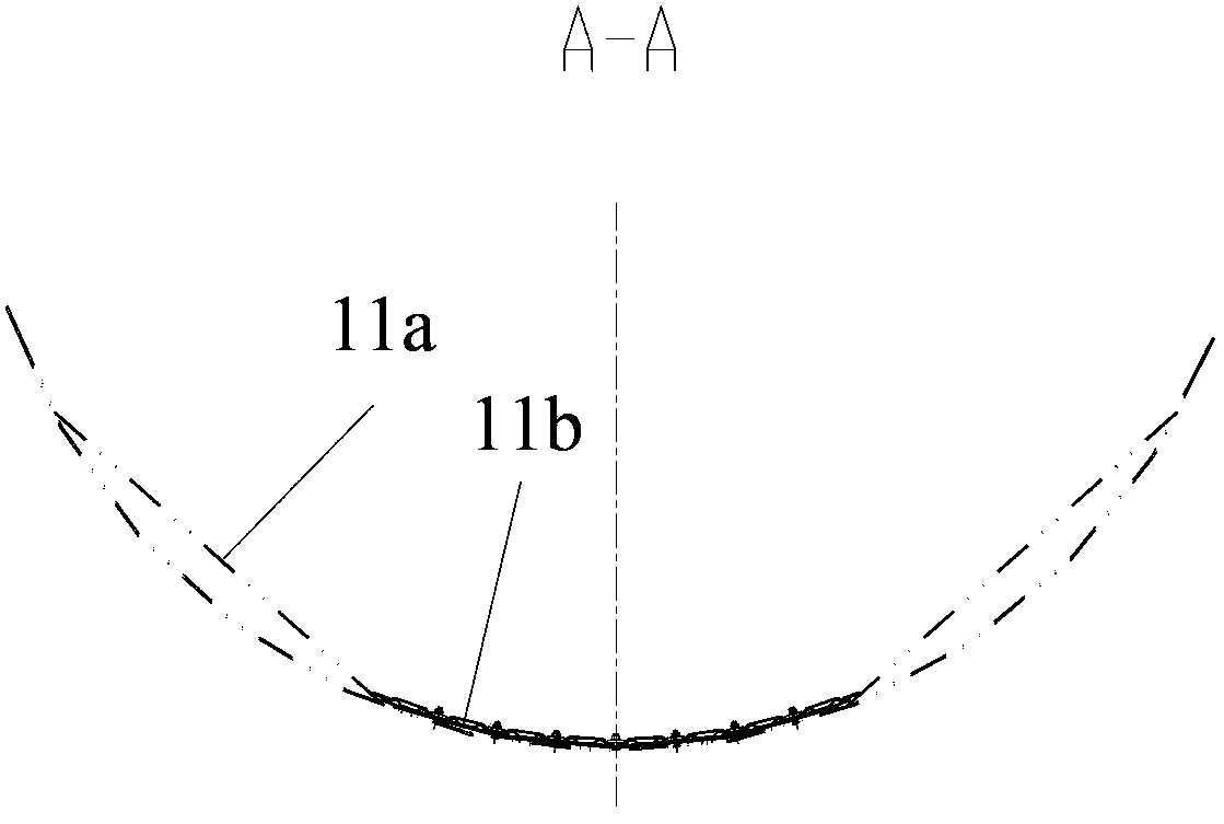
[0024] image 3 Shown is a schematic front view of the tank body and fluidization system of the powder material transport vehicle in an embodiment of the present invention. Figure 3A shown as image 3 A schematic top view of the tank and fluidization system of the transporter shown. Figure 3B shown along Figure 3A Schematic cross-section of line C-C in middle. Such as image 3 , Figure 3A and Figure 3B As shown, the powder material transportation vehicle includes a tank body 10 and a fluidization system 20 . The tank body 10 includes a body 12 and caps 11 disposed at two ends of the body 12 . The fluidization system 20 includes a plurality of air-permeable bags 21 located at the bottom of the tank body 10 , a plurality of pipe joints 22 respectively connected to each air-permeable bag 21 , and an end slide 23 arranged at the head 11 of the tank body 10 . The end slide plate 23 is arranged at the bottom of the head 11 and forms an air chamber 24 with the end head 1...


PUM


Abstract

The invention discloses a fluidization system for a powder and particle material transport vehicle and the powder and particle material transport vehicle. The fluidization system is arranged in a tank body of the powder and particle material transport vehicle and is used for fluidizing and unloading powder and particle materials; the tank body comprises a body and seal heads arranged at both ends of the body; the fluidization system comprises a plurality of ventilating bags which are arranged at the bottom of the tank body and extend towards the center from both ends of the tank body; the ventilating bags can be filled with air and blow air towards the powder and particle materials; and an included angle between the horizontal plane and the tangent line of the section arc of the tank body corresponding to the outer edges of the outermost ventilating bags in the ventilating bags is greater than 31 degrees. The fluidization system uses the ventilating bags to replace lateral sliding plates in the prior art and has the advantages of light dead weight, simplicity for manufacturing and indirect increase of the volume of the tank body. Moreover, separate control of air sources of two or four outermost ventilating bags at both left and right sides in the ventilating bags can be implemented, so that unloading can be implemented under the condition that the air sources are insufficient.

Description

technical field [0001] The invention relates to a fluidization system of a transport vehicle and a powder material transport vehicle, in particular to a fluidization system and a powder material transport vehicle for transporting powder materials. Background technique [0002] The transport vehicles used to transport powder materials generally have a fluidization system. As the core part of the powder material transport vehicle, the fluidization system is set inside the tank of the transport vehicle and is used in the process of unloading powder materials. Fluidize the material to achieve discharge. [0003] figure 1 and Figure 1A It is a schematic diagram of front view and top view of the fluidization system of an existing transport vehicle, Figure 1B for along Figure 1A A schematic cross-sectional view of line A-A. Such as figure 1 , Figure 1A and Figure 1B As shown, and can also refer to the background technology part of the patent with the notification numbe...

Claims


Application Information

Patent Timeline
Patent Type & Authority Patents(China)
IPC IPC(8): B65G69/06B60P3/22
Inventor 梁尚平李威窦国平
Owner CHINA INTERNATIONAL MARINE CONTAINERS (GROUP) CO LTD
Why Eureka
Try Eureka