Steel wire rope winding device

A hoisting device and wire rope technology, applied in the direction of hoisting device, spring mechanism, etc., can solve the problems of excessive deflection angle of wire rope, affecting the normal use of pillow changing machine, and the failure of real synchronization between drum and rope guide wheel, etc.

Active Publication Date: 2014-05-21
上海瑞纽机械股份有限公司
View PDF11 Cites 8 Cited by
  • Summary
  • Abstract
  • Description
  • Claims
  • Application Information

AI Technical Summary

Problems solved by technology

The main problems of this electric rope reel are: because the rope is retracted and unwound is a two-way process, and it is affected by various factors such as manufacturing errors, normal wear and tear, the section of the wire rope is not ideally circular, and the wire rope slips on the guide pulley. Under the circumstances, the drum and the guide wheel cannot be truly synchronized, and there is always a phenomenon that the effect is good when the rope is drawn, but the effect is poor when the rope is released, or the effect is good when the rope is released, but the effect is poor when the rope is drawn.
[0004] If the hoisting device adopts existing electric rope reels such as CN2587839, there will be the following two problems: 1. because the hoisting device on the left side and the center distance of the pulley parts are small, the excessive deflection angle of the wire rope will occur situation
2. The hoisting devices on both sides have no gravity assistance in the process of receiving and releasing the rope, and must be manually pulled, otherwise there will be rope chaos
The above two problems have affected the normal use of the pillow changing machine

Method used


Image

  • Steel wire rope winding device
  • Steel wire rope winding device
  • Steel wire rope winding device

Examples


Embodiment Construction

[0029] The technical solutions of the present invention will be further described below in conjunction with the accompanying drawings and embodiments.

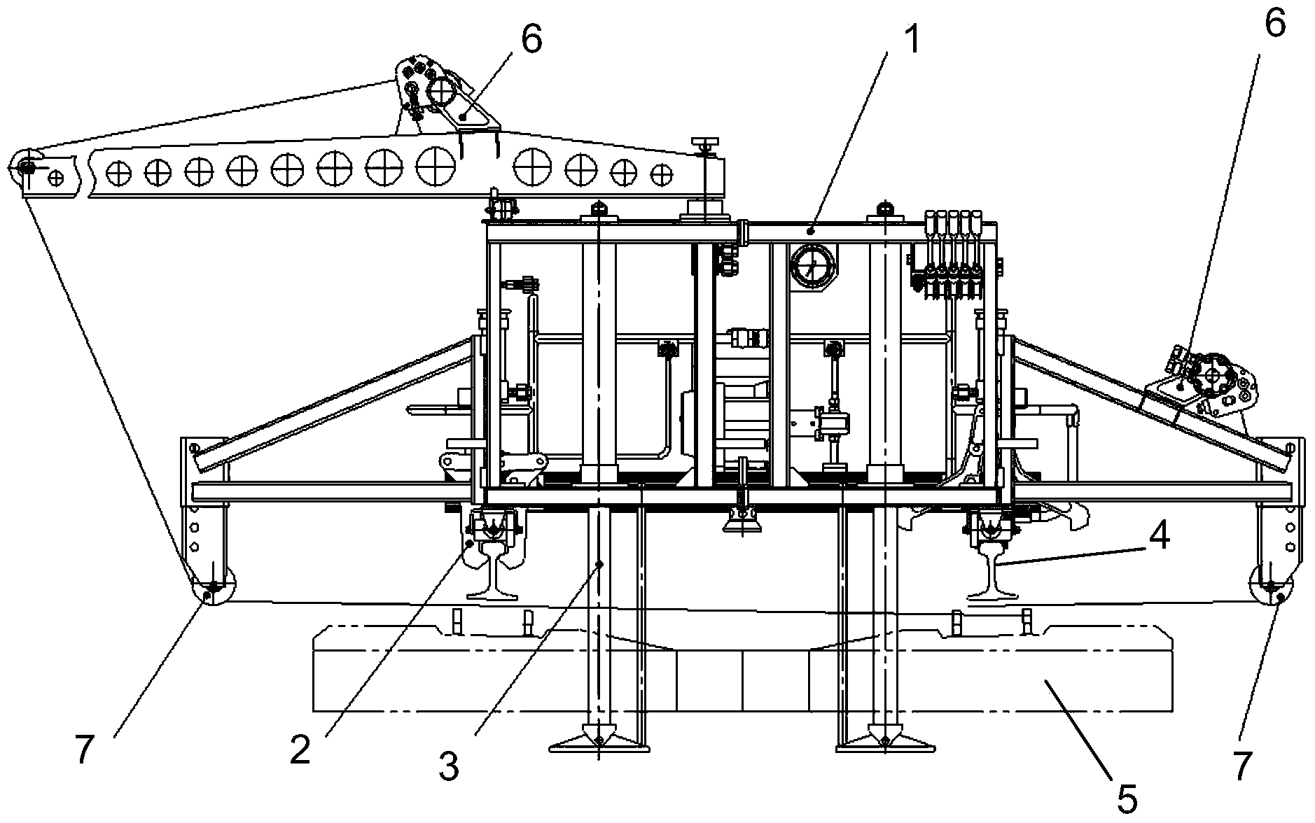
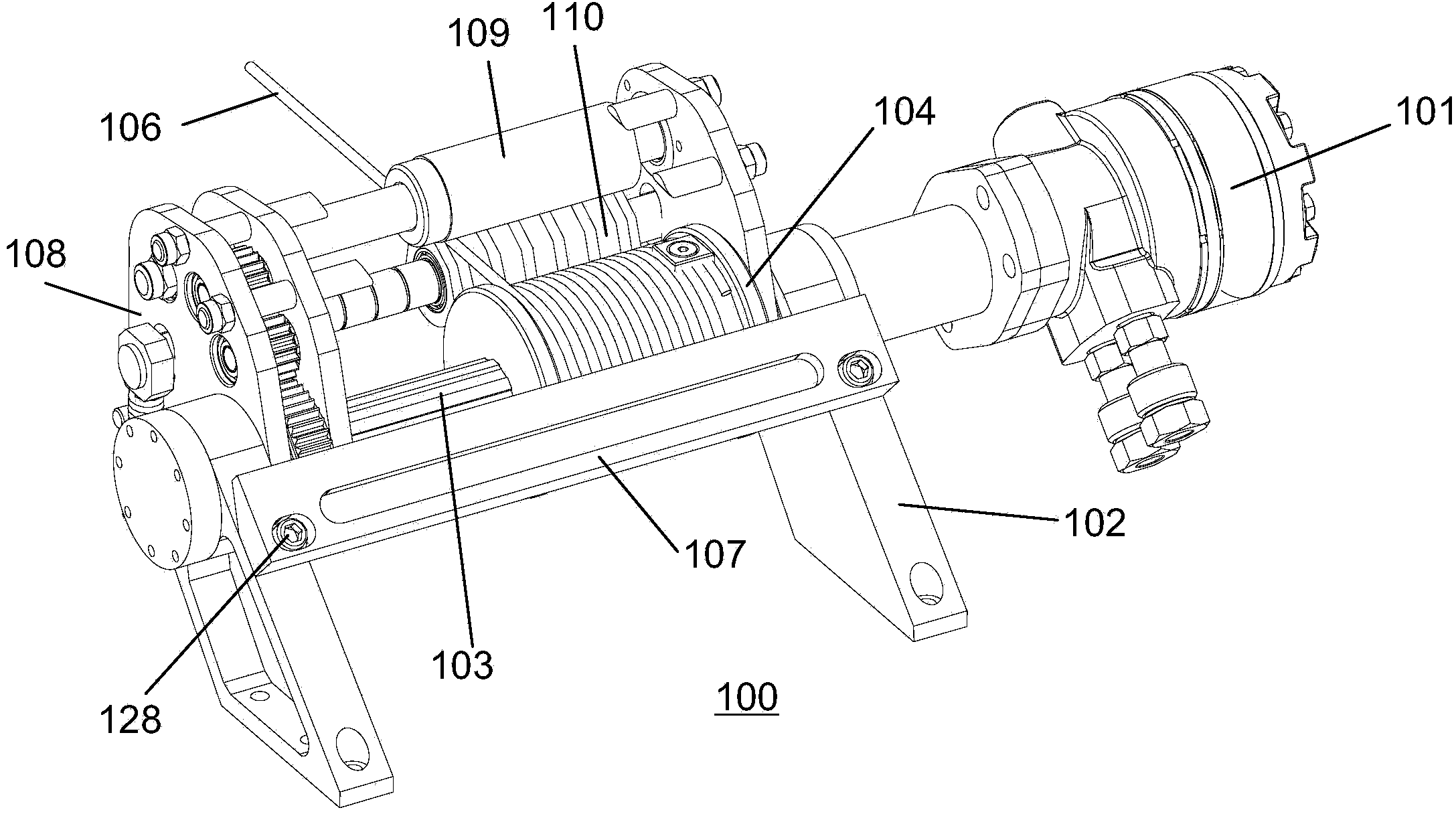
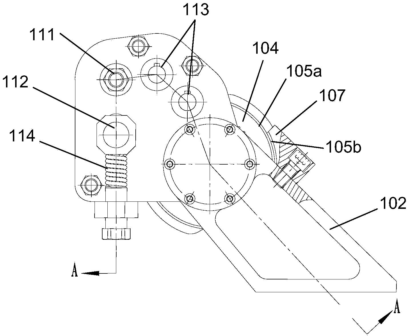
[0030] see Figure 2-6 As shown in the figure, the wire rope hoisting device 100 of the present invention is the same as the prior art in that it also includes a power component 101, a fixed frame 102, a spline shaft 103 arranged on the fixed frame 102 and connected to the power component 101, and a movable sleeve. The wire rope reel 104 on the spline shaft 103, the power part 101 can use a hydraulic motor or other power device to drive the spline shaft 103 to rotate, and the fixed frame 102 is provided with a pair of self-aligning bearings 105 to install the spline shaft 103 , the wire rope reel 104 is used to wind the wire rope 106 , and through the self-aligning bearing 105 , the non-concentric error of the bearing hole of the fixing frame 102 caused by manufacturing can be eliminated. Different from the prior art, the wir...


PUM


Abstract

The invention discloses a steel wire rope winding device which comprises a power part, a fixing frame, a spline shaft, a steel wire rope reel, a nut plate, a rotary frame, a rope guiding wheel and a rope pressing wheel. The spline shaft is arranged on the fixing frame and connected with the power part, and the steel wire tope reel is movably arranged on the spline shaft in a sleeved mode. Due to the fact that the reel is meshed with the nut plate and can move along the spline shaft, when a steel wire rope is wound into or unwound out of a pulley and the reel, declination is completely avoided, in other words, the declination angle of the steel wire rope is zero degree, and therefore even if limitation of the structural size exists, for example, the center distance between the reel and the pulley is quite small, the phenomenon that due to the excessively-large declination angle of the steel wire rope, the steel wire rope is impacted and rubbed with the lateral side of a rope groove or the steel wire rope jumps out of the groove can be avoided.

Description

technical field [0001] The invention relates to hoisting equipment, more specifically, to a wire rope hoisting device. Background technique [0002] Patent Publication No. CN2587839 discloses an electric rope reel, which is made up of a motor, a reducer, a rope reel, a rope guide, a steel wire rope and a casing. The main problems of this electric rope reel are: because the rope is retracted and unwound is a two-way process, and it is affected by various factors such as manufacturing errors, normal wear and tear, the section of the wire rope is not ideally circular, and the wire rope slips on the guide pulley. Under the circumstances, there is no real synchronization between the reel and the guide wheel, and there is always a phenomenon that the effect is good when the rope is taken in, but the effect is poor when the rope is released, or the effect is good when the rope is released, but the effect is poor when the rope is taken in. [0003] see figure 1 , figure 1 Shown i...

Claims


Application Information

Patent Timeline
Patent Type & Authority Applications(China)
IPC IPC(8): B66D1/395B66D1/08B66D1/14
Inventor 宋正忠顾学安陈光军周其成
Owner 上海瑞纽机械股份有限公司
Why Eureka
Try Eureka