
Three-cylindrical rolling rotor type compressor

A rolling rotor type, compressor technology, applied in the field of refrigeration compressors, can solve problems such as inability to fit in, crankshaft eccentric shaft components are not produced, and achieve the effects of rotational balance, low vibration and noise, and balanced overall load torque.

Inactive Publication Date: 2014-05-21
吴月广
View PDF7 Cites 8 Cited by
  • Summary
  • Abstract
  • Description
  • Claims
  • Application Information

AI Technical Summary

Problems solved by technology

Since the rolling rotor is installed outside each eccentric shaft, when the eccentric shafts are staggered by 120° from each other, the crankshaft and the eccentric shaft require extremely high strength and precision and are processed in one piece, so the rolling rotor cannot be inserted into the one in the middle of the crankshaft Eccentric shaft
[0014] For example, in patent CN1142368C, the engineer tried to solve the assembly problem of the eccentric shaft and the rolling rotor in the middle of the crankshaft of the three-cylinder rolling rotor compressor, and invented a crankshaft eccentric shaft assembly with multi-part groups. However, based on the strength and accuracy, the assembled crankshaft The eccentric shaft assembly is not currently in production

Method used


Image

  • Three-cylindrical rolling rotor type compressor
  • Three-cylindrical rolling rotor type compressor
  • Three-cylindrical rolling rotor type compressor

Examples


Embodiment Construction

[0036] The present invention will be further described below in conjunction with the accompanying drawings.

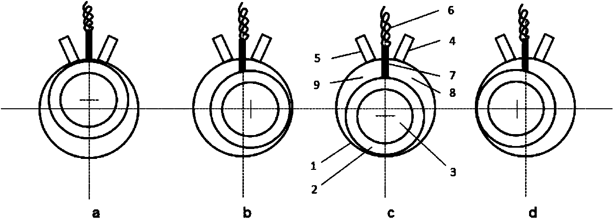
[0037] like Figure 4 , the angular arrangement of the three cylinders used in the present invention is not evenly divided by 360°, wherein the sliding vanes (4, 5) of two adjacent cylinders (1, 2) are arranged at an angle staggered by 120°, and the third cylinder 3 The slide plate 6 and the front two cylinders are respectively staggered by 60°.

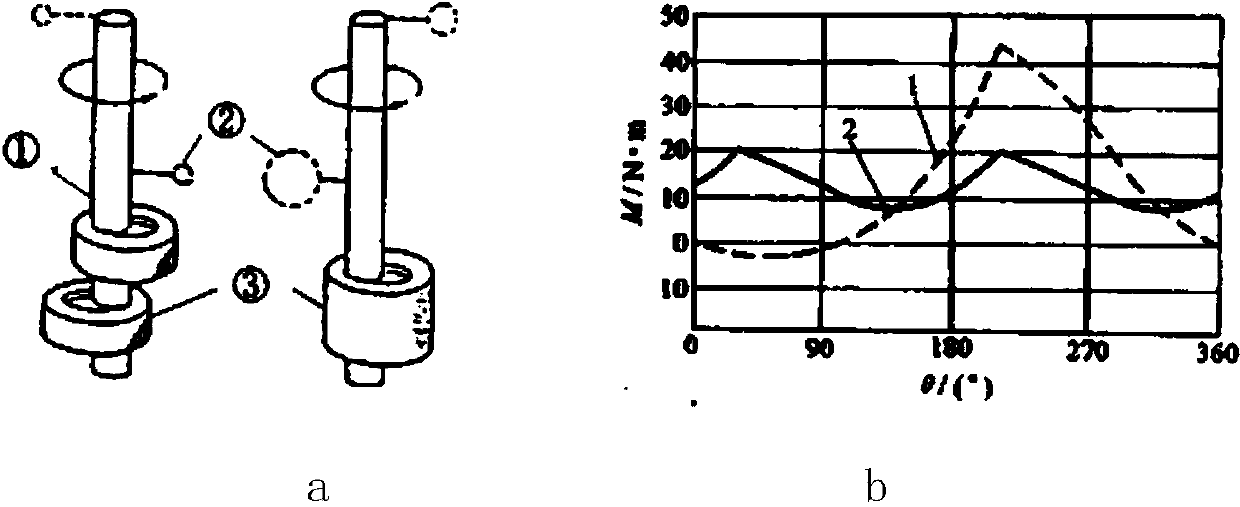
[0038] like Figure 5 a, The crankshaft 1 and eccentric shafts (2, 3, 4) used in the present invention are integrally processed, and the eccentric directions of two adjacent eccentric shafts (2, 3) are exactly the same. The eccentric direction of the third eccentric shaft 4 is designed to be staggered by 180° from the two eccentric shafts with the same eccentric direction.

[0039] like Figure 5 a, Two eccentric shafts (2, 3) with exactly the same eccentric direction can be designed to be closer to the crankshaft 1 insta...


PUM


Abstract

The invention discloses a three-cylindrical rolling rotor type compressor. The three-cylindrical rolling rotor type compressor comprises a liquid storage device, a sealed container, an electromotor, and an air cylinder component; a stator of the electromotor is fixed in the sealed container; a rotor of the electromotor is connected to an eccentric shaft for driving the air cylinder component comprising three air cylinder units; angles of slide sheets of two adjacent air cylinders are staggered with 120 degrees, and a slide sheet of a third air cylinder and each of the slide sheets of the other two air cylinders are staggered with 60 degrees; two adjacent eccentric shafts on an integrated processed crankshaft has the complete same eccentric directions, and a third eccentric shaft and each of the other two eccentric shafts are staggered with 180 degrees; the centric shaft which is staggered with 180 degrees individually is provided with a torque balance mechanism; two air cylinders the slide sheets of which are staggered with 120 degrees and the two eccentric shafts with the completely same eccentric directions are installed at the same side; the eccentric shaft which is staggered with 180 degrees and the third air cylinder are assembled at the other side. By adopting the three-cylindrical roller rotor compressor provided by the invention, the displacement and the power of the rolling rotor type compressor are increased, the vibration of load torque is reduced, and the vibration and the noise are reduced.

Description

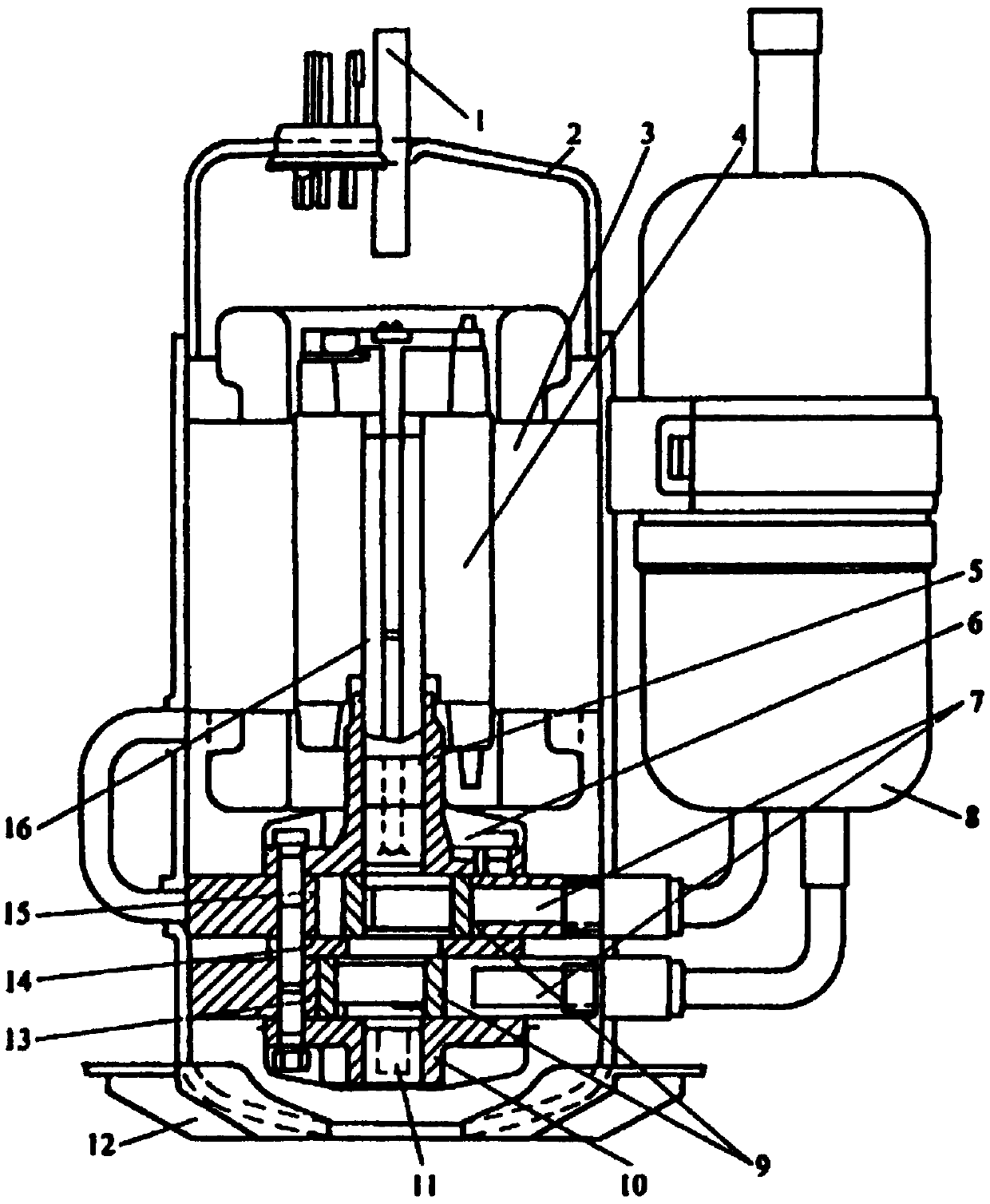
technical field [0001] The invention relates to the technical field of refrigeration compressors for air conditioners and refrigerators, in particular to the structure of a rolling rotor compressor. Background technique [0002] As the core component of air conditioners and refrigerators, there are many types of refrigeration compressors, among which the rolling rotor compressor is one of the mainstream models, and there are usually two types: horizontal and vertical. According to the number of cylinder blocks, rolling rotor compressors are also divided into two types: single cylinder and double cylinder. [0003] According to different internal functions, the rolling rotor compressor is composed of four major parts: a liquid accumulator, a sealed container, and a motor part and a cylinder assembly arranged in the sealed container. [0004] like figure 1 : the stator 3 of the motor is fixed in the casing 2 of the airtight container, and the rotor 4 of the motor is connecte...

Claims


Application Information

Patent Timeline
IPC IPC(8): F04C18/356F16C3/06F16C3/18
CPCF16C2360/42
Inventor 吴月广
Owner 吴月广
Learn More