Sensor system

A sensor and sensor unit technology, applied in the field of sensor systems, can solve the problems of reduced response speed, longer light projection period of photoelectric sensors, and deterioration of measurement accuracy.

Active Publication Date: 2014-05-21
ORMON CORP
View PDF7 Cites 11 Cited by
  • Summary
  • Abstract
  • Description
  • Claims
  • Application Information

AI Technical Summary

Problems solved by technology

Therefore, in a system in which photosensors with a short light emission period and photosensors with a long light emission period can be mixed, the light emissio...

Method used


Image

  • Sensor system
  • Sensor system
  • Sensor system

Examples


Embodiment Construction

[0042] Hereinafter, embodiments of the present invention will be described with reference to the drawings. In the following description, the same reference numerals are assigned to the same components. Their names and functions are also the same. Therefore, their detailed descriptions are not repeated.

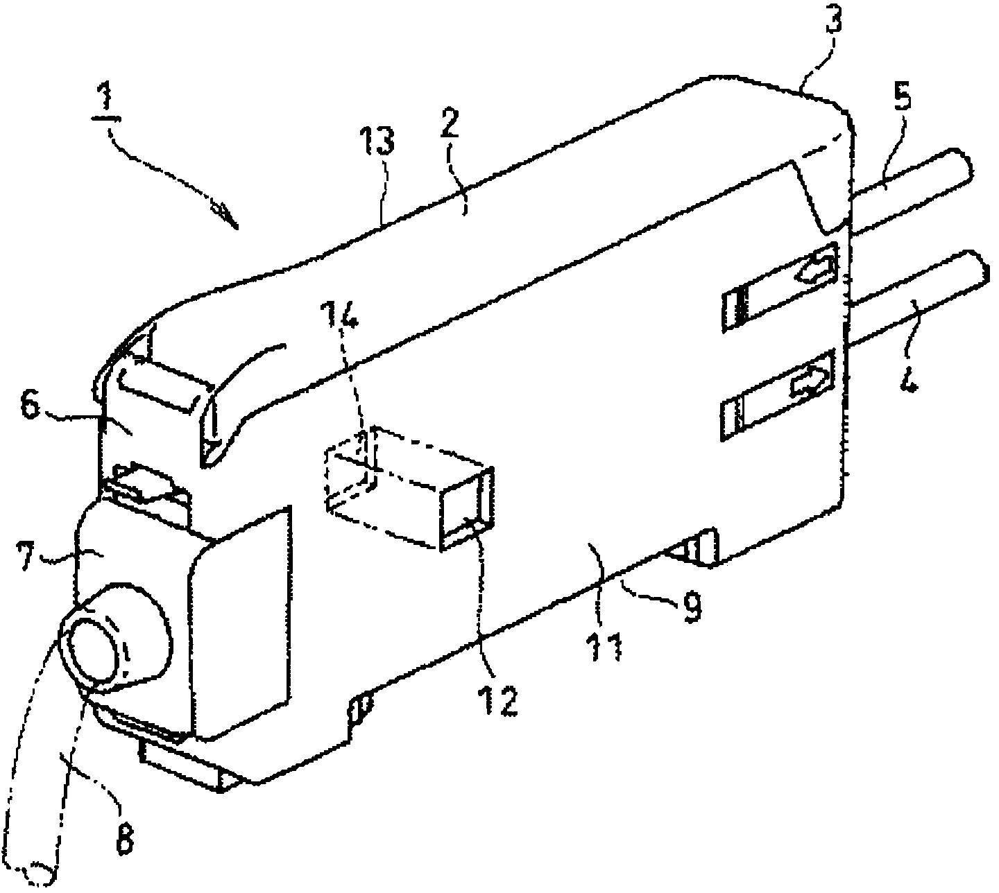
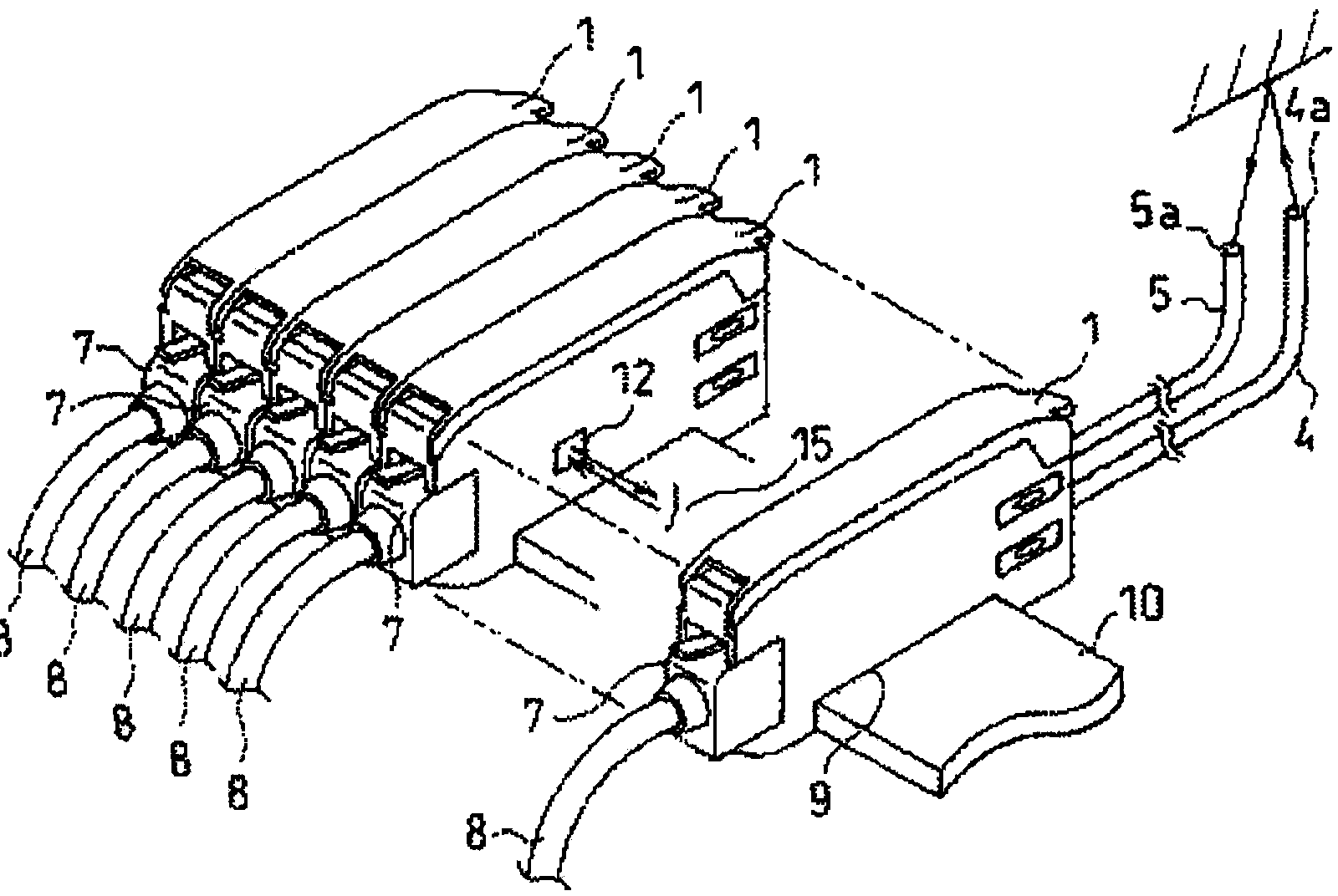
[0043] refer to figure 2 , the sensor system of this embodiment is constituted by a plurality of types of photosensor units 1 including a plurality of photosensor units 1 . As an example, the types are classified according to operation (light projection) time, wavelength, cycle, amplitude, frequency, and the like of projected light. That is, the light projection time, the wavelength, cycle, amplitude, frequency, and the like of projected light differ for each type. The sensor system may also include an ultrasonic sensor unit, a proximity sensor unit, etc. in addition to the photoelectric sensor unit 1 , or may replace the photoelectric sensor unit 1 with an ultrasonic sen...


PUM


Abstract

The invention provides a sensor system. In the sensor system including a plurality of photoelectric sensor units, a light projecting period suitably determined for each type is provided and mutual interference is prevented between sensor units of the same type. The sensor system includes the plurality of sensor units that are coupled in such a manner that signal transmission among the sensor units is possible. Each of the sensor units retains type information indicating a sensor type of the respective sensor unit, and sets a unique identification number of the respective sensor unit by signal transmission among the sensor units. Each of the sensor units operates after a delay time determined according to the identification number of the respective sensor unit elapses with a synchronization signal as a starting point. The synchronization signal is transmitted with a predetermined period from one of the plurality of sensor units that has a specific identification number. The delay time of each of the sensor units is determined such that an operating period of the respective sensor unit matches with a predetermined period, which is determined individually for each sensor type, and such that the delay time differs from the delay time of any other sensor unit having the same sensor type.

Description

technical field [0001] The present invention relates to a sensor system, and particularly relates to a technique for controlling the light projection period of each sensor unit in a sensor system having a plurality of sensor units. Background technique [0002] In a production line or the like, the presence or absence of a workpiece (detection object) is determined based on a physical quantity such as the amount of light received by a sensor. Regarding physical quantities, detection is performed at various places. That is, a plurality of sensors are provided. In this case, for example, the light receiving part of a photosensor may be arranged near the light receiving part of another photosensor. In this case, the light projected from a certain photoelectric sensor may enter the light receiving part of another photoelectric sensor, which may degrade the determination accuracy. In view of such a problem, a method of preventing mutual interference is used by making the opera...

Claims


Application Information

Patent Timeline
IPC IPC(8): G01D5/58G08C23/04G01S17/04G01S17/87
CPCG01S17/87G01S7/003G01S7/497G01S7/4818H03K2217/94094G01V8/20H04L12/40019H04L12/4015H03K17/941H03K17/943H03K2217/94104H03K2217/94108G01S17/04G01J1/4228
Inventor 饭田雄介井口康二岸场秀行权藤清彦
Owner ORMON CORP
Why Eureka
Try Eureka