

Method and device for activating on-board unit
An on-board unit and activation device technology, applied in the field of communication, can solve the problems of increasing the operational complexity and increasing the hardware cost of the OBU system, and achieve the effects of increasing the operational complexity and making the operation simple and easy.
- Summary
- Abstract
- Description
- Claims
- Application Information
AI Technical Summary
Problems solved by technology
Method used
Image

Examples
Embodiment Construction
[0026] Hereinafter, the present invention will be described in detail with reference to the drawings and examples. It should be noted that, in the case of no conflict, the embodiments in the present application and the features in the embodiments can be combined with each other.
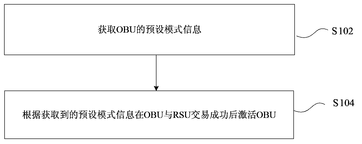
[0027] figure 1 is a flow chart of a method for activating a vehicle-mounted unit according to an embodiment of the present invention. Such as figure 1 As shown, the method may include the following processing steps:
[0028] Step S102: Obtain the preset mode information of the OBU;
[0029] Step S104: Activate the OBU after the OBU and the RSU are successfully traded according to the acquired preset mode information.
[0030] In the related art, the way of activating the OBU not only increases the hardware cost of the OBU system, but also increases the operation complexity. use as figure 1 In the method shown, the preprocessing mode of the OBU is set in advance. After obtaining the preset mode...
PUM
 Abstract
Description
Claims
Application Information