Data card and multi-mode broadband antenna system

An antenna system and broadband antenna technology, applied in the field of data cards, can solve the problems of covering the full frequency band of LTE and the difficulty of data cards

Active Publication Date: 2014-05-21
HUAWEI DEVICE CO LTD
View PDF3 Cites 4 Cited by
  • Summary
  • Abstract
  • Description
  • Claims
  • Application Information

AI Technical Summary

Problems solved by technology

[0005] The embodiment of the present invention provides a multi-mode broadband antenna system for a data card and a data card equipped with the multi-mode broadband an

Method used


Image

  • Data card and multi-mode broadband antenna system
  • Data card and multi-mode broadband antenna system
  • Data card and multi-mode broadband antenna system

Examples


Embodiment 1

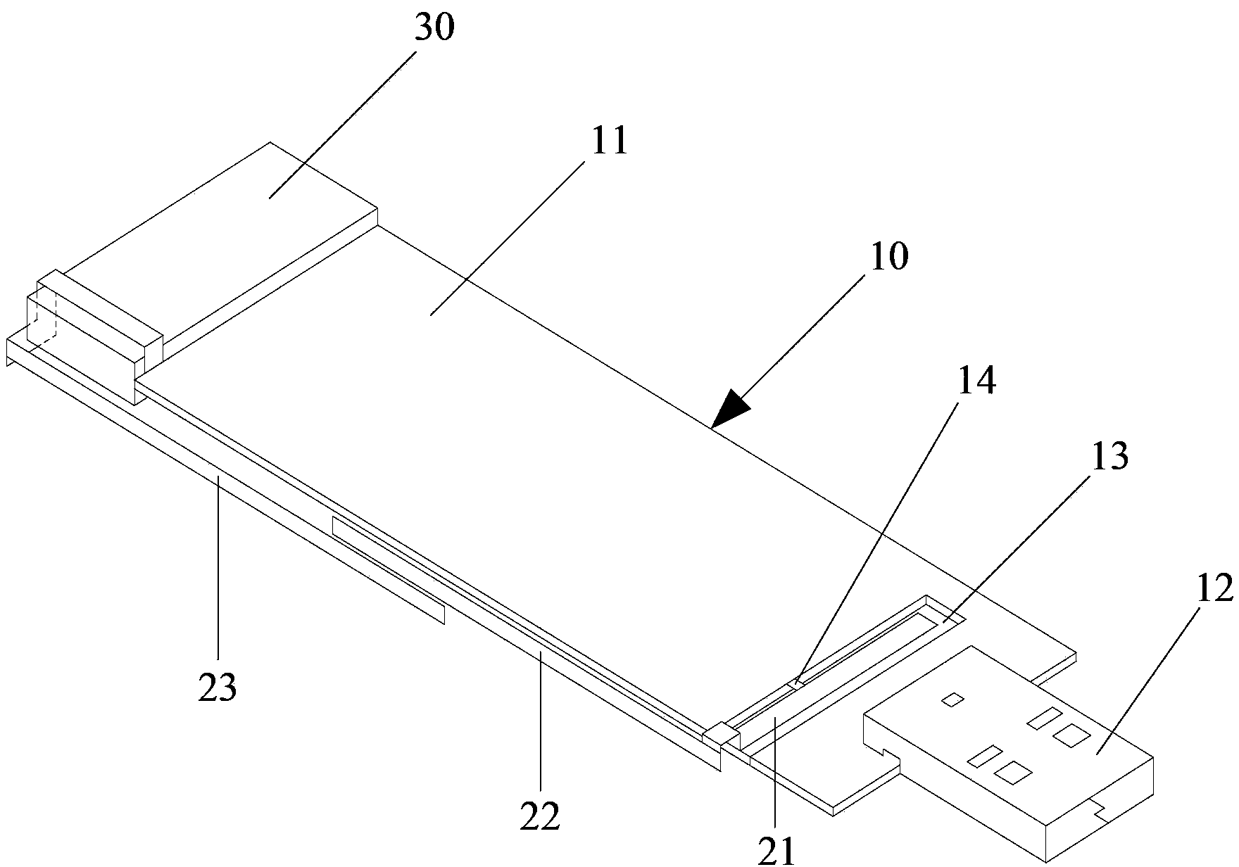
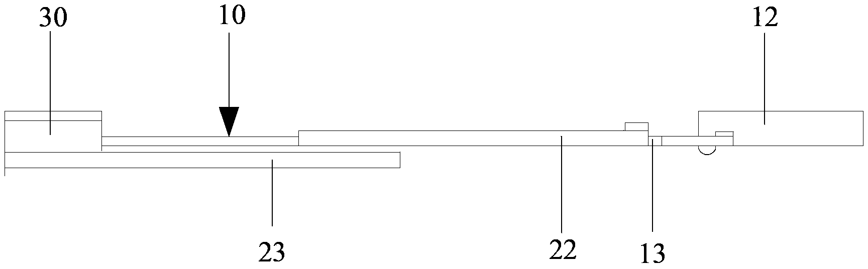
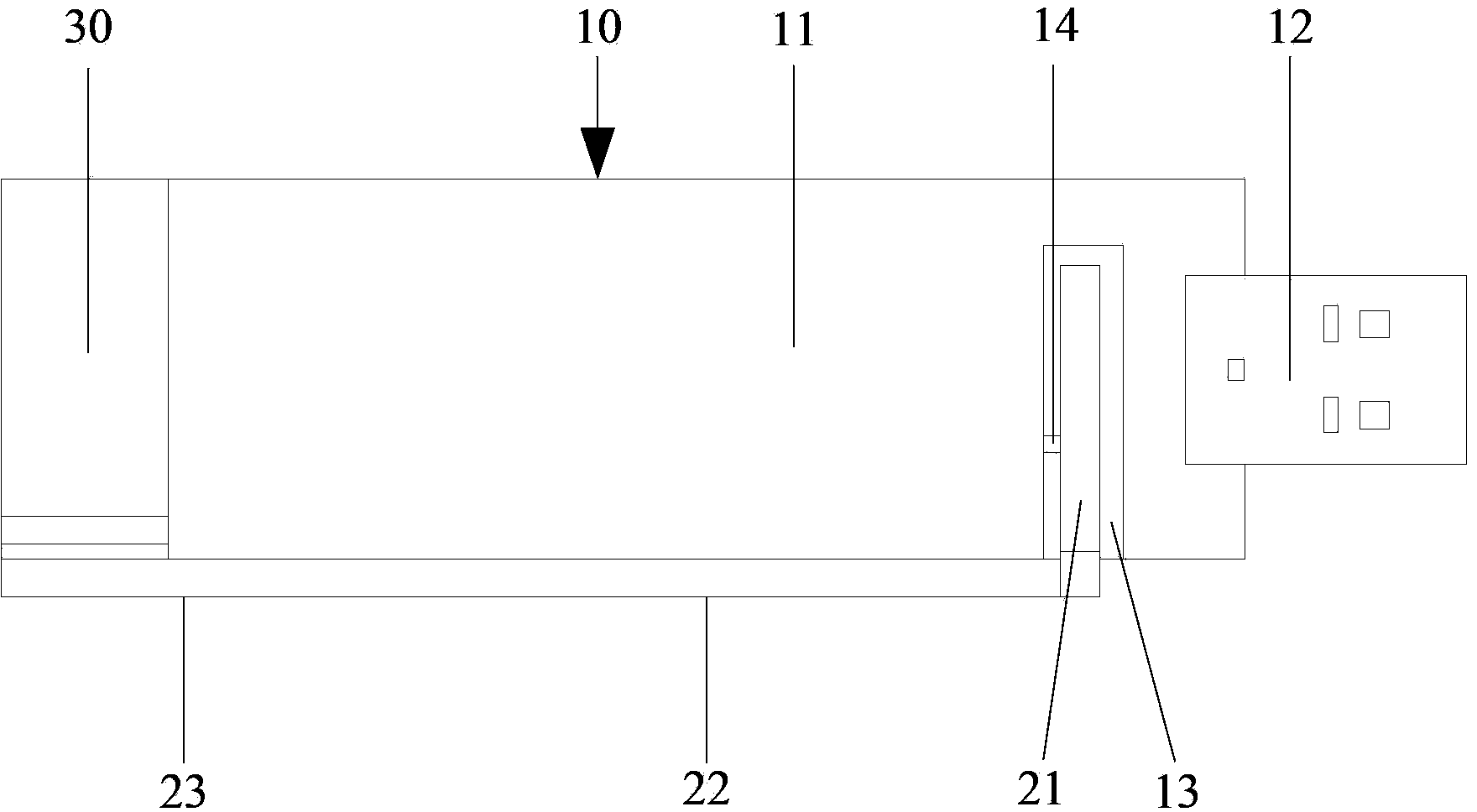
[0038] Such as figure 1 As shown, the multi-mode broadband antenna system for a data card provided by the embodiment of the present invention includes a PCB board 10 , and a first radiator 21 , a second radiator 22 and a third radiator 23 in strip shape.

[0039] One side of the PCB board 10 is covered with a metal ground 11, and the USB plug 12 of the data card is arranged on one short side of the PCB board 10; on one long side of the PCB board 10, there is a place close to the USB plug 12 for accommodating the first radiator 21 grooves 13 . In this embodiment, the first radiator 21 is strip-shaped, and the groove 13 is also strip-shaped, which is compatible with the first radiator 21 .

[0040] The first radiator 21 is located in the groove 13 and is connected to the transceiver module (not shown in the figure) of the data card through the feeder 14 . The first end of the first radiator 21 is located at the bottom of the groove 13 , and the second end of the first radiator...

Embodiment 2

[0055] This embodiment is basically the same as Embodiment 1, as Figure 5 and Figure 6 As shown, the first radiator 21 is located in the groove 13 of the PCB 10 , and the first end of the second radiator 22 is electrically connected to the second end of the first radiator 21 at the edge of the PCB 10 . The second end of the second radiator 22 is coupled to the first end of the third radiator 23 in the form of a slot. After the second end of the third radiator 23 is bent, it bypasses the plastic bracket 30 in the data card and the One end of the metal ground 11 away from the USB plug 12 is electrically connected.

[0056] The difference between this embodiment and Embodiment 1 is that: the second radiator 22 and the third radiator 23 are located on the same horizontal plane, and the second end of the second radiator 22 is connected to the third radiator 23 through a bent part. The first end of the slit forms a gap, which produces a capacitive coupling effect.

[0057] Comp...

Embodiment 3

[0059] This embodiment is basically the same as Embodiment 1, as Figure 7 , Figure 8 and Figure 9 As shown, the first radiator 21 is located in the groove 13 of the PCB 10 , and the first end of the second radiator 22 is electrically connected to the second end of the first radiator 21 at the edge of the PCB 10 . After being bent, the second end of the third radiator 23 bypasses the plastic bracket 30 in the data card and is electrically connected to the end of the metal ground 11 away from the USB plug 12 .

[0060] The difference between this embodiment and Embodiment 1 is that: the second radiator 22 and the third radiator 23 are disposed on the long side where the groove 13 of the PCB 10 is located. The second radiator 22 is located on the front of the PCB 10, the third radiator 23 is located on the back of the PCB 10, and the second end of the second radiator 22 and the first end of the third radiator 23 are respectively on the two sides of the PCB 10. Overlapping p...


PUM


Abstract

This invention discloses a multi-mode broadband antenna system of a data card and a data card which is provided with the same, belonging to the technology communication filed and solving the existing technology problem that the present data card is hard to cover LTD full spectrum band under the condition that the volume of the data card is small. The multi-mode broadband antenna system comprises a PCB board, a first irradiator, a second irradiator and a third irradiator. One side of the PCB board is covered by a metal ground; a USB plug of the data card arranged on a short side of the PCB board; a groove for receiving the first irradiator is formed on the long side of the PCB board and near the USB plug; the first irradiator is positioned within the groove and is connected to a transmit-receive module through a feeder line; the first terminal of the first irradiator is arranged on the bottom of the groove, and the second terminal of the first irradiator is electrically connected to the first terminal of the second irradiator; the second terminal of the second irradiator is coupled to the first terminal of the third irradiator; and the second terminal of the third irradiator is connected to the metal ground. This invention is applied to the data card.

Description

technical field [0001] The invention belongs to the technical field of communication, and in particular relates to a multi-mode broadband antenna system for a data card and a data card equipped with the multi-mode broadband antenna system. Background technique [0002] An antenna system is provided inside the data card, and the USB plug of the data card can be conveniently inserted into a USB port of a computer. Users can log on to the Internet anytime and anywhere to query massive information, which brings great convenience to life and work. [0003] The bandwidth characteristics of the antenna system in the data card have an important impact on the radiation characteristics, and the antenna system realizes signal propagation and energy radiation based on the principle of resonance. If an antenna system can resonate in multiple frequency bands, the antenna system can work in multiple frequency bands, which is called a multi-mode broadband antenna system. The current devel...

Claims


Application Information

Patent Timeline
IPC IPC(8): H01Q1/22H01Q5/01H01Q25/04H01Q5/10
Inventor 徐慧梁隆仲莹孙树辉兰尧
Owner HUAWEI DEVICE CO LTD
Why Eureka
Try Eureka