Software debugging method and device for SFP (small form pluggable) ONU (optical network unit)

A technology for optical network unit and software debugging, which is applied to the selection device, electrical components, selection device, etc. of the multiplexing system, and can solve the problems of difficult SFPONU software debugging of the terminal

Inactive Publication Date: 2014-05-21
HISENSE BROADBAND MULTIMEDIA TECH
View PDF6 Cites 17 Cited by
  • Summary
  • Abstract
  • Description
  • Claims
  • Application Information

AI Technical Summary

Problems solved by technology

[0005] The invention provides a software debugging method and device for a small optical network unit SFP ONU, which is used to solve

Method used


Image

  • Software debugging method and device for SFP (small form pluggable) ONU (optical network unit)
  • Software debugging method and device for SFP (small form pluggable) ONU (optical network unit)

Examples


Embodiment Construction

[0022] In order to make the purpose, technical solutions and advantages of the embodiments of the present invention clearer, the technical solutions in the embodiments of the present invention will be clearly and completely described below in conjunction with the drawings in the embodiments of the present invention. Obviously, the described embodiments It is a part of embodiments of the present invention, but not all embodiments. Based on the embodiments of the present invention, all other embodiments obtained by persons of ordinary skill in the art without making creative efforts belong to the protection scope of the present invention.

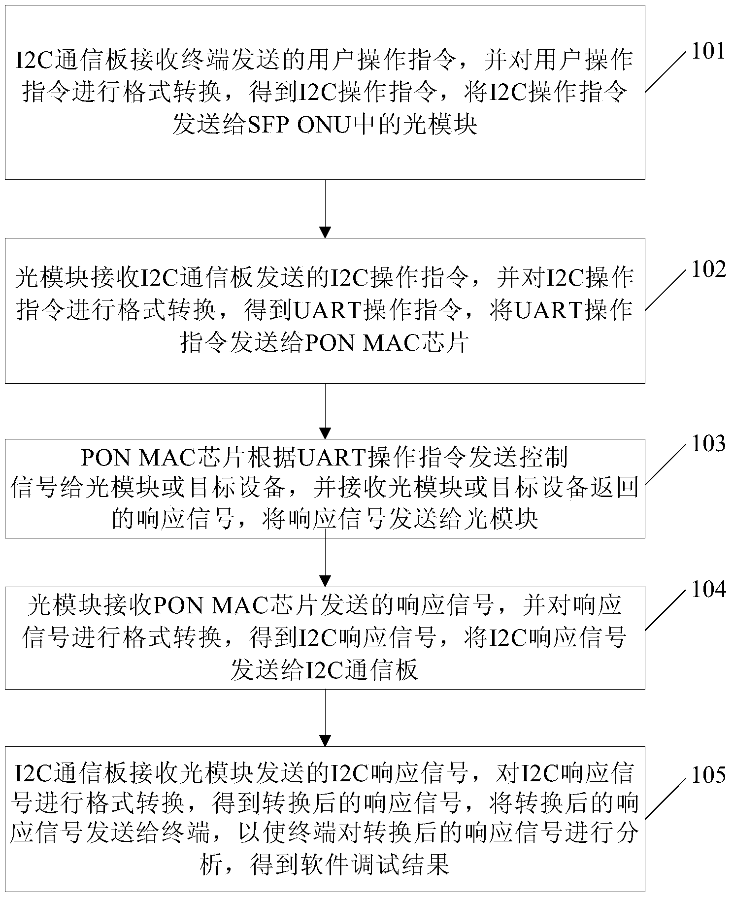
[0023] figure 1 A flowchart of an embodiment of a software debugging method of a small optical network unit SFP ONU provided by the present invention, such as figure 1 shown, including:

[0024] 101. The I2C communication board receives the user operation instruction sent by the terminal, converts the format of the user operation instructio...


PUM


Abstract

The invention relates to a software debugging method and device for an SFP (small form pluggable) ONU (optical network unit). An I2C communication board is additionally arranged between the SFP ONU and a terminal and used for switching over UART (universal asynchronous receiver transmitter) or USB (universal serial bus) data and I2C data, an optical module in the SFP ONU is used for switching over the I2C data and the UART data, so that user operation instructions transmitted by the terminal and used for debugging software can be transmitted by the aid of the I2C communication board and the optical module to a PON MAC chip, the PON MAC chip transmits control signals to the optical module or a target device according to the user operation instructions and receives response signals returned by the optical module or the target device, and then the response signals can be transmitted to the terminal sequentially through the optical module and the I2C communication board, so that the response signals are analyzed by the terminal to obtain software debugging results.

Description

technical field [0001] The invention relates to the field of optical network equipment, in particular to a software debugging method and device for a small optical network unit SFP ONU. Background technique [0002] Currently, an optical network unit (Optical Network Unit, ONU) includes: an optical module, an Ethernet interface, a PON MAC chip, and a Flash memory. Among them, the optical module includes optical components such as an optical receiving module, an optical transmitting module, or an integrated optical transceiver module, which are used to receive optical signals under the control of the PON MAC chip, convert optical signals into electrical signals and forward them; The electrical signal is converted into an optical signal and forwarded. The Ethernet interface is an Ethernet data transmission interface, which is used to send the electrical signal converted by the optical module to the terminal connected to the Ethernet interface, or forward the electrical signal...

Claims


Application Information

Patent Timeline
IPC IPC(8): H04L12/24H04Q11/00
Inventor 乐毅李江涛赵立国尤青山
Owner HISENSE BROADBAND MULTIMEDIA TECH
Why Eureka
Try Eureka