
Pipe bender

The technology of a pipe bending machine and a frame is applied in the field of pipe bending manufacturing equipment, which can solve the problems of complex structure and easy flattening of pipe fittings, and achieve the effects of small size, compact structure design and reduced manufacturing cost.

Inactive Publication Date: 2014-05-28
SHANGHAI SUQIAO MECHANICAL EQUIP
View PDF0 Cites 10 Cited by
  • Summary
  • Abstract
  • Description
  • Claims
  • Application Information

AI Technical Summary

Problems solved by technology

[0003] The technical problem to be solved by the present invention is: in order to overcome the problems of the existing pipe bending machine with complex structure and easy flattening of pipe fittings during use, a pipe bending machine with simple structure, convenient use and good bending effect of pipe fittings is provided.

Method used


Image

  • Pipe bender

Examples


Embodiment Construction

[0008] Now, the present invention will be described in further detail in conjunction with the accompanying drawings. These drawings are all simplified schematic diagrams, which only illustrate the basic structure of the present invention in a schematic manner, so they only show the configurations related to the present invention. After reading the content of the present invention, those skilled in the art can make various modifications to the present invention, and these equivalent changes and modifications also fall within the scope of protection defined by the present invention.

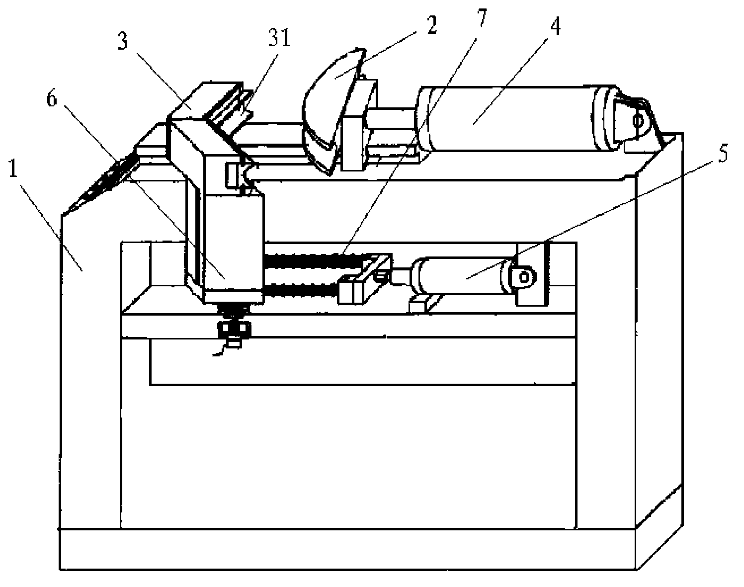
[0009] Such as figure 1 As shown, a pipe bending machine includes a frame 1, a power transmission mechanism fixedly arranged on the frame 1, the frame 1 is provided with a driving wheel 2, and the power transmission mechanism has a hydraulic cylinder 4 and a damping cylinder 5, The driving wheel 2 is connected with the hydraulic cylinder 4, and the end corresponding to the driving wheel 2 on the f...


PUM


Abstract

The invention discloses a pipe bender comprising a frame and a power transmission mechanism fixedly arranged on the frame. A driving wheel is arranged on the frame. The power transmission mechanism comprises a hydraulic cylinder and a damping cylinder. The driving wheel is connected with the hydraulic cylinder. A driven module is arranged at one end, corresponding to the driving wheel, of the frame. An arc-shaped groove is formed in one side, corresponding to the driving wheel, of the driven module and is matched with the outer edge of the driving wheel. The driven module can be slidably arranged on a die holder which can be rotationally arranged on the frame. The lower portion of the die holder is connected with the damping cylinder. A pipe is positioned between the driving wheel and the arc-shaped groove of the driven module when the pipe bender is used for bending the pipe, and the driven module rotates along with the driving wheel during operation of the driving wheel, so that the pipe is not easy to flatten; the pipe bender is compact in structural design and low in size, and production cost is greatly reduced.

Description

technical field [0001] The invention relates to the technical field of pipe bending manufacturing equipment, in particular to a pipe bending machine. Background technique [0002] The pipe bending machine in the prior art usually consists of a driving part and a driven part arranged on the frame. The power transmission mechanism fixed on the frame is connected with the driving part. When working, the pipe is placed between the driving part and the driven part. Between the moving parts, the power transmission mechanism drives the driving part to move around the driven part, so that the pipe is bent. This kind of pipe bending machine has some disadvantages in the process of use: the pipe fittings are easily crushed, the mechanical structure is relatively complicated, the equipment is bulky, and the manufacturing cost is high. Contents of the invention [0003] The technical problem to be solved by the present invention is to provide a pipe bender with simple structure, conv...

Claims


Application Information

Patent Timeline
Patent Type & Authority Applications(China)
IPC IPC(8): B21D7/024
Inventor 黄正华
Owner SHANGHAI SUQIAO MECHANICAL EQUIP
Learn More