LED (light-emitting diode) wall wash lamp and assembling method thereof

A technology of an LED wall washer and an assembly method, applied in the lighting field, can solve the problems of inability to disassemble, cannot be disassembled again, poor sealing, etc., and achieves the effects of avoiding short service life, improving utilization, and facilitating disassembly

Active Publication Date: 2013-04-03
CHANGZHOU INST OF LIGHT IND TECH +1
View PDF3 Cites 9 Cited by
  • Summary
  • Abstract
  • Description
  • Claims
  • Application Information

AI Technical Summary

Problems solved by technology

[0002] The existing LED wall washer usually consists of a lamp body, a lampshade and an LED lamp. The LED lamp is installed in the lampshade, and the lampshade is installed in the lamp body. Usually, the method of squeezing glass glue is used, and the sealing is poor, resulting in poor waterproof performance of the LED wall washer, which affects the use of the LED wall washer, and can no longer be disassembled; that is, if the lamp group fails, the light transmission cannot be disassembled Board replacement light set

Method used


Image

  • LED (light-emitting diode) wall wash lamp and assembling method thereof
  • LED (light-emitting diode) wall wash lamp and assembling method thereof
  • LED (light-emitting diode) wall wash lamp and assembling method thereof

Examples


Embodiment 1

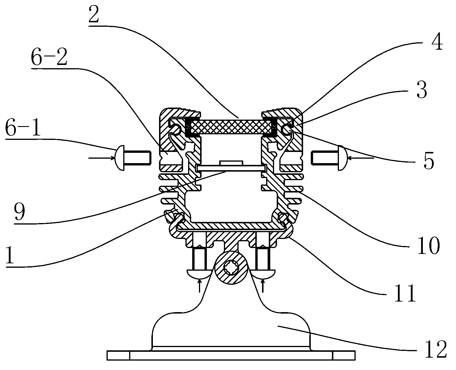
[0057] See figure 1 , 2 , an LED wall washer lamp, comprising: a lamp body 1, a light-transmitting plate 2 arranged on the top light outlet of the lamp body 1, and two "F"-shaped hinge bars 3 symmetrically installed on both sides of the lamp body , the hinge bead 3 is distributed along the length direction of the lamp body 1; a circular groove 4 is arranged on the outside of the top adjacent to the lamp body 1, and the circular groove 4 is distributed along the length direction of the lamp body 1; The inner surface of the neck of the hinge bead 3 is provided with ribs 5 distributed along the length direction, the ribs 5 are cylindrical, and are suitable for rotating with the circular groove 4; The end extending inwardly is suitable for compressing the edge of the light-transmitting plate 2; the lower end of the hinge bar 3 is provided with a bolt for controlling the end to compress the light-transmitting plate 2; Next, the lower end of the hinge bar 3 is adapted to leave the...

Embodiment approach 1

[0059] Embodiment 1: the bolt is a locking bolt 6-1, and a threaded hole 6-2 is opened on the lower end of the hinge bead 3, and the locking bolt 6-1 is drilled into the threaded hole 6-2, And control the size of the gap between the lower end of the hinge bead 3 and the side of the lamp body 1, so that the end presses the light-transmitting plate 2; the bolts can also be round-headed bolts or flat-headed bolts, and the bolts can also be called for the screws.

Embodiment approach 2

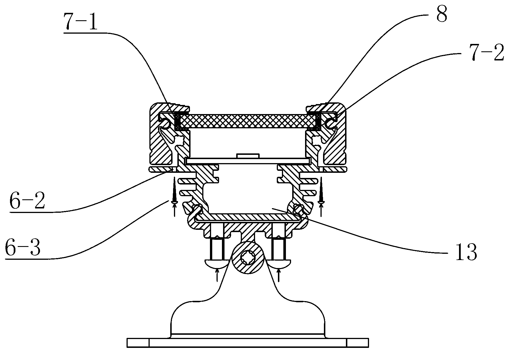
[0060] Embodiment 2: The bolt is a self-tapping bolt 6-3, and a threaded hole 6-2 is provided on the lamp body 1 and below the gap between the lower end of the hinge bead 3 and the side of the lamp body 1. The self-tapping bolt 6-3 is drilled into the threaded hole 6-2, and the size of the gap between the lower end of the hinge bar 3 and the side surface 1 of the lamp body is controlled, so that the end presses the light-transmitting plate 2 tightly.

[0061] The lamp body 1 is provided with a support portion suitable for placing the light-transmitting plate, and the first support surface 7-1 and the second support surface 7-2 included in the support portion are provided with a lower waterproof strip groove (in the figure Not marked), the lower waterproof strip groove is suitable for placing the lower waterproof strip, and the lower waterproof strip groove body is distributed along the length direction of the lamp body 1 .

[0062] The lower waterproof strip can be an L-shaped...


PUM


Abstract

The invention relates to an LED (light-emitting diode) wall wash lamp, which comprises a lamp body, a light-transmitting plate and two hinge pressing bars, wherein the light-transmitting plate is arranged on a light-emitting opening at the top of the lamp body; the two hinge pressing bars are symmetrically arranged at the two sides of the lamp body, and are distributed along the length direction of the lamp body; circular grooves are arranged near outside of the top of the lamp body; the circular grooves are distributed along the length direction of the lamp body; ribs which are distributed along the length direction are arranged near the inner side surface of a neck part of the hinge pressing bar; the ribs are in a cylindrical shape, and are in running fit with the circular grooves; the tail end extending inwards at the top of each hinge pressing bar is suitable for compressing the edge of the light-transmitting plate; the lower end part of each hinge pressing bar is provided with a bolt used for controlling the tail end to compress the light-transmitting plate; under the action of the bolt, the lower end part of each hinge pressing bar is suitable for the side away from the lamp body; and the ribs rotate in the circular grooves, so that the light-transmitting plate is compressed by the tail end.

Description

technical field [0001] The invention relates to the lighting field, in particular to an LED wall washer suitable for assembly or disassembly. Background technique [0002] The existing LED wall washer usually consists of a lamp body, a lampshade and an LED lamp. The LED lamp is installed in the lampshade, and the lampshade is installed in the lamp body. Usually, the method of squeezing glass glue is used, and the sealing is poor, resulting in poor waterproof performance of the LED wall washer, which affects the use of the LED wall washer, and can no longer be disassembled; that is, if the lamp group fails, the light transmission cannot be disassembled Board replacement lamp set. Therefore, how to realize the convenience of installation and disassembly between the light-transmitting plate and the lamp body is a technical problem in this field. Contents of the invention [0003] The technical problem to be solved by the present invention is to provide an LED wall washer su...

Claims


Application Information

Patent Timeline
Patent Type & Authority Applications(China)
IPC IPC(8): F21S8/00F21V17/12F21V29/02H05B37/02F21Y101/02F21V29/67F21Y115/10
CPCF21S8/00F21S8/03F21S8/08F21V14/00F21V17/10F21V17/104F21V17/107F21V17/12F21V19/001F21V19/0015F21V23/00F21V23/003F21V31/005F21W2131/107H02J3/18H02J3/1814H02M7/49H05B45/00H05B47/10Y02B20/72Y02E40/10Y02E40/30
Inventor 周健姚庆文卢灿
Owner CHANGZHOU INST OF LIGHT IND TECH
Why Eureka
Try Eureka