
Automatic and precise positioning lifting and unloading device for machine tools

A precise positioning and automatic technology, applied in metal processing and other directions, can solve the problems of difficult automatic mass production of machine tools, affecting the working efficiency of processing machine tools, and high cost of blanking devices, achieving simple and easy adjustment and control, simple structure and economical. The effect of resources

Active Publication Date: 2016-04-27
LOTUS STATIONERY
View PDF6 Cites 0 Cited by
  • Summary
  • Abstract
  • Description
  • Claims
  • Application Information

AI Technical Summary

Problems solved by technology

[0002] In the prior art, machine tools that produce large quantities of high-precision complex parts are equipped with corresponding blanking devices. The efficiency of the blanking device directly affects the processing efficiency of the machine tool. Taking the pen industry as an example, when producing pen tips It is necessary to transport the pen material to the station of the machine tool processing mechanism through the unloading device. It is difficult for the traditional unloading device of the pen-making processing machine tool to realize the precise positioning of the conveying mechanism during the round-trip process, resulting in the cost of the unloading process. It takes a lot of time to adjust the blanking position, so the work efficiency is low, which directly affects the work efficiency of the processing machine tool, and it is difficult to realize the automatic mass production of the machine tool. There are also some automatic control blanking devices that can meet the continuity of blanking, but cannot The accuracy of its blanking is well realized, and the cost of automatic control of the blanking device is huge

Method used


Image

  • Automatic and precise positioning lifting and unloading device for machine tools
  • Automatic and precise positioning lifting and unloading device for machine tools

Examples


Embodiment Construction

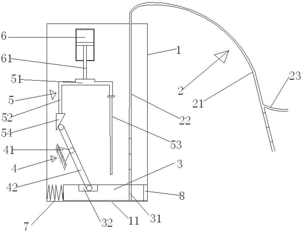
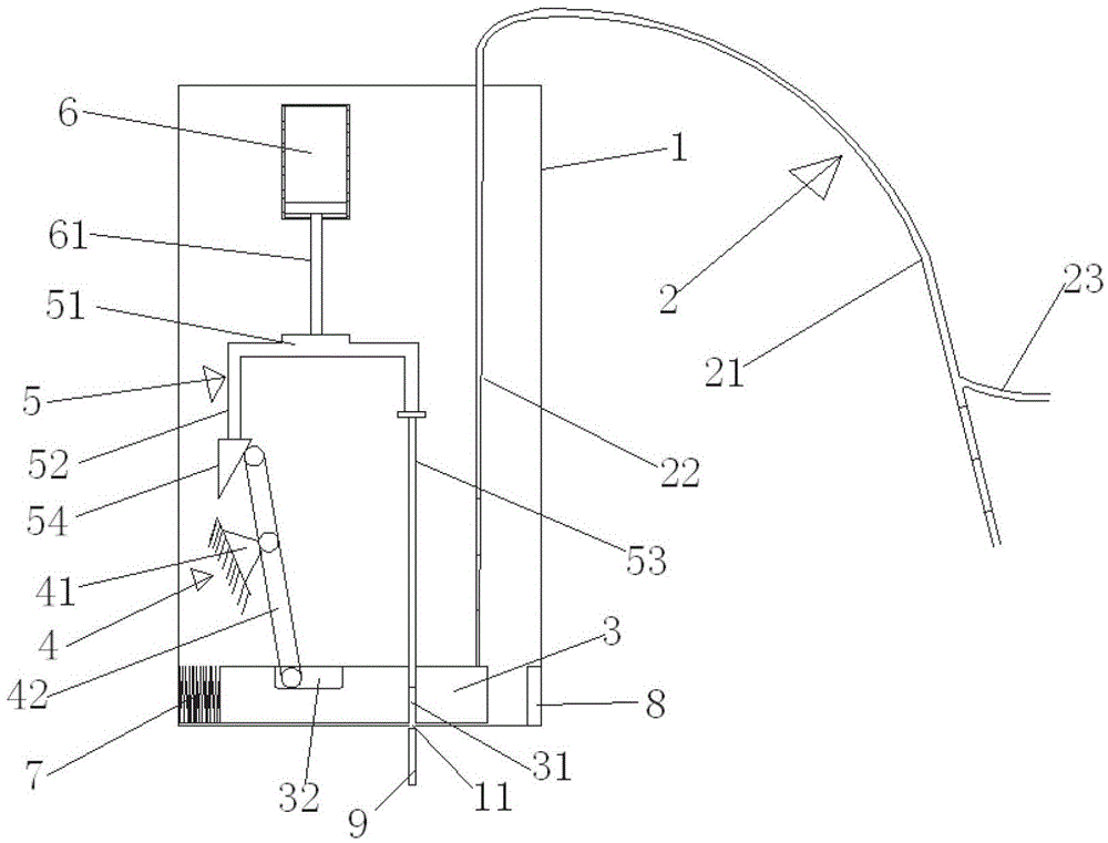
[0024] Such as figure 1 and figure 2 As shown, an automatic and precise positioning lifting and unloading device for a machine tool includes a body 1, a feeding mechanism 2 and a strip slider 3. Based on the direction of use, the slider is horizontally arranged on the bottom of the body, and one end The end face is against one side of the body, and the other end face is positioned and connected to the other side of the body through an elastic device. The end of the slider facing away from the elastic device is vertically provided with a first feed through hole 31, and the first feed through hole 31 is vertically provided on the end of the slider. The upper end of a feeding through hole communicates with the feeding mechanism, and the feeding mechanism can transport the raw material 9 to be processed into the first feeding through hole. A lever mechanism 4, a connecting rod, and Mechanism 5 and cylinder 6 correspond to the connecting rod mechanism, and the bottom of the body ...


PUM


Abstract

The invention discloses an automatic precise positioning rising and discharging device for a machine tool. The device comprises a machine body, a feeding mechanism and a strip-shaped slider. The strip-shaped slider is transversely arranged on the bottom of the machine body, the end face of one end of the slider is butted against one side of the machine body, the end face of the other end of the slider is connected with the other side of the machine body in a positioning manner through an elastic device, good compression and return effect can be achieved, one end, back to the elastic device, of the slider is provided with a first feeding through hole, the upper end of the first feeding through hole is communicated with the feeding mechanism, the feeding mechanism can convey to-be-machined raw materials into the first feeding through hole, a lever mechanism, a connecting bar mechanism and an air cylinder are arranged above the slider sequentially, and automatic accurate positioning and discharging of the machine tool can be carried out by linkage action of the air cylinder, the connecting bar mechanism and the lever mechanism and matched return action of the elastic device. Besides, since adjustment of the air cylinder is simple, easy to control, safe and rapid, traveling speed of the slider can be adjusted according to actual requirements, and automatic working and machining efficiency is further improved.

Description

technical field [0001] The invention relates to a blanking device, in particular to an automatic and precise positioning lifting blanking device for machine tools. Background technique [0002] In the prior art, machine tools that produce large quantities of high-precision complex parts are equipped with corresponding blanking devices. The efficiency of the blanking device directly affects the processing efficiency of the machine tool. Taking the pen industry as an example, when producing pen tips It is necessary to transport the pen material to the station of the machine tool processing mechanism through the unloading device. It is difficult for the traditional unloading device of the pen-making processing machine tool to realize the precise positioning of the conveying mechanism during the round-trip process, resulting in the cost of the unloading process. It takes a lot of time to adjust the blanking position, so the work efficiency is low, which directly affects the work...

Claims


Application Information

Patent Timeline
Patent Type & Authority Patents(China)
IPC IPC(8): B23Q7/00
CPCB23Q7/00B23Q7/006
Inventor 黄小喜曾清木陆宪明吴瑛戟张端周杨崇倡
Owner LOTUS STATIONERY
Learn More