Conveying cart device
A trolley device and frame technology, which is applied in the direction of transportation and packaging, trolleys, multi-axis trolleys, etc., can solve the problems of affecting the efficiency of material transportation, inconvenient adjustment of the angle of materials or designated unloading positions, etc., and achieve simple structure and reduced space Size requirements, the effect of easy loading and unloading
- Summary
- Abstract
- Description
- Claims
- Application Information
AI Technical Summary
Problems solved by technology
Method used
Image

Examples
Embodiment 1
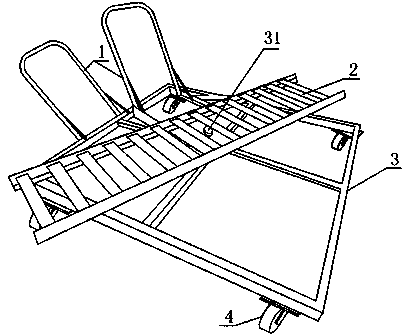
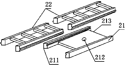
[0021] Figure 1 to image 3 , a transport trolley device provided by the present invention includes a frame 3, a plurality of rollers 4 are fixedly connected to the bottom of the frame 3, and a rotating bracket 2, and a bearing portion 31 is also provided on the frame 3 , the rotating bracket 2 is connected with the frame 3 through the bearing part 31 , the rotating bracket 2 is located above the frame 3 , and the rotating bracket 2 can rotate with the bearing part 31 .
[0022] The provided rotating bracket 2 is used to place materials, and the rotating bracket 2 is rotatably arranged relative to the frame 3. When loading materials, it is convenient to rotate the rotating bracket 2 according to the shape and placement position of the materials to adapt to the material in the present invention. When unloading the material, according to the unloading placement point of the material, the material rotates with the rotating bracket 2 to adapt to the placement point. The above set...
Embodiment 2
[0024] This embodiment is further limited on the basis of embodiment 1: as shown in Figure 1 to image 3 , for the convenience of the present invention, the user applies push and pull to the material during the material delivery process, so as to facilitate the rotation of the rotating bracket 2. The frame 3 and the rotating bracket 2 are all fixedly connected with a push handle 1.
Embodiment 3
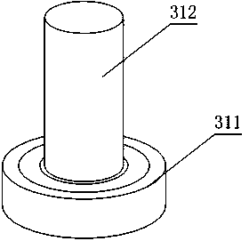
[0026] This embodiment is further limited on the basis of embodiment 1: as shown in Figure 1 to image 3 In order to simplify the structure of the bearing part 31 , the bearing part 31 includes a bearing 311 and a rotating shaft 312 fixed on the inner ring of the bearing 311 , and the rotating bracket 2 is fixedly connected to the rotating shaft 312 . Further, there are more than one bearings 311, all of which are deep groove ball bearings. The above adopting the bearing form of rolling friction is conducive to the compactness of the connection between the rotating bracket 2 and the frame 3. At the same time, the deep groove ball bearing has a long service life and low price, which is beneficial to reduce the use and maintenance costs of the present invention.
PUM
 Abstract
Description
Claims
Application Information
 - R&D
- Intellectual Property
- Life Sciences
- Materials
- Tech Scout
- Unparalleled Data Quality
- Higher Quality Content
- 60% Fewer Hallucinations
Browse by: Latest US Patents, China's latest patents, Technical Efficacy Thesaurus, Application Domain, Technology Topic, Popular Technical Reports.
© 2025 PatSnap. All rights reserved.Legal|Privacy policy|Modern Slavery Act Transparency Statement|Sitemap|About US| Contact US: help@patsnap.com