Hydraulic power chuck for automatic drilling machine

A technology of hydraulic power and drilling rigs, which is applied in the direction of drilling pipes, drill pipes, earthwork drilling, etc., to achieve the effect of easy hydraulic control, small size and compact structure

Active Publication Date: 2014-05-28
HUNAN SEA BULL GEOLOGICAL EXPLORATION CO LTD
View PDF8 Cites 11 Cited by
  • Summary
  • Abstract
  • Description
  • Claims
  • Application Information

AI Technical Summary

Problems solved by technology

Most of the existing hydraulic power chucks for automatic drilling rigs are general-purpose for land drilling rigs, and they are considered to be applicable to many specifications of drilling tools, and the requirements for external dimensions are relatively loose. Heavy, not suitable for deep hole core sampling drilling rigs with automatic loading and unloading rods working on the seabed, or small automatic drilling rigs with relatively single specifications for drilling pipes and drilling tools in narrow shafts
Especially for deep hole core sampling drilling rigs with automatic loading and unloading rods working on the seabed, the hydraulic power chuck only needs to adapt to a single drill pipe specification, but it must be installed and fixed in its frame as a whole without hindering the installation and operation of other components. Work, the weight should be as light as possible. In this case, it is difficult to directly apply the existing land general-purpose hydraulic power chuck

Method used


Image

  • Hydraulic power chuck for automatic drilling machine
  • Hydraulic power chuck for automatic drilling machine
  • Hydraulic power chuck for automatic drilling machine

Examples


Embodiment 1

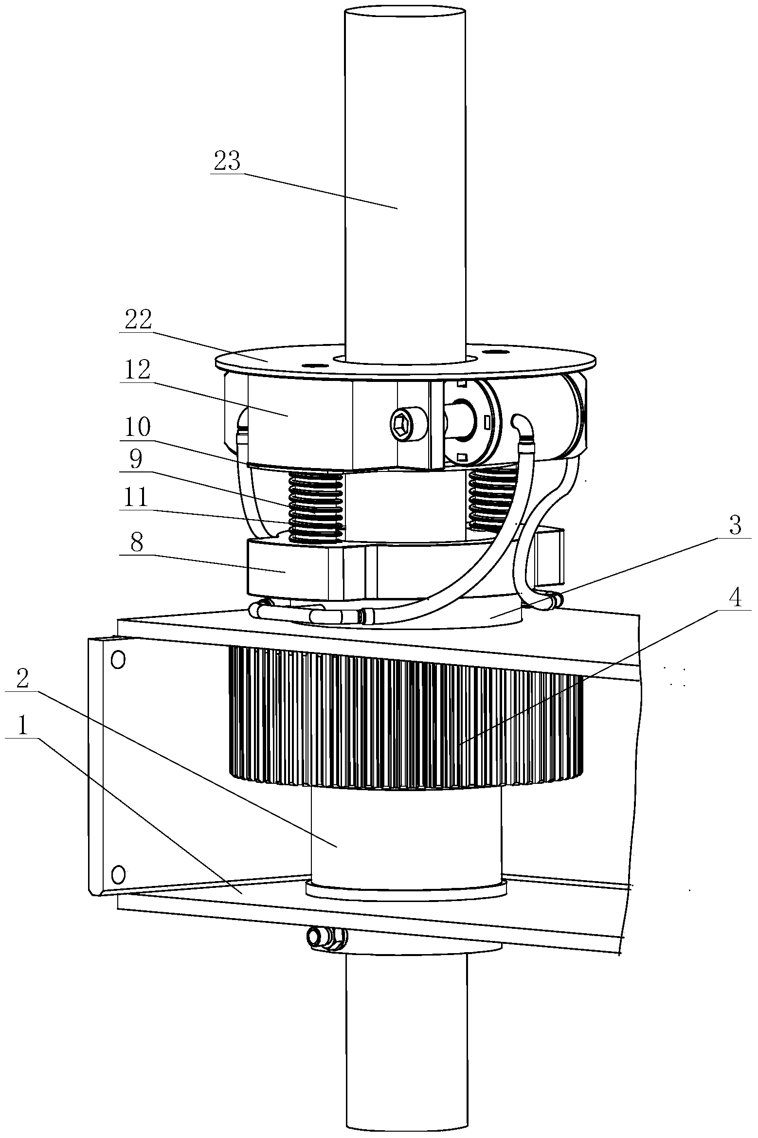
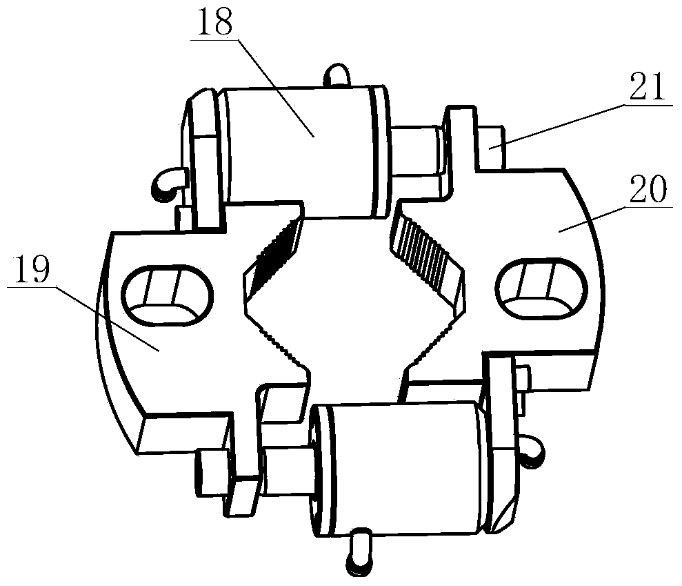
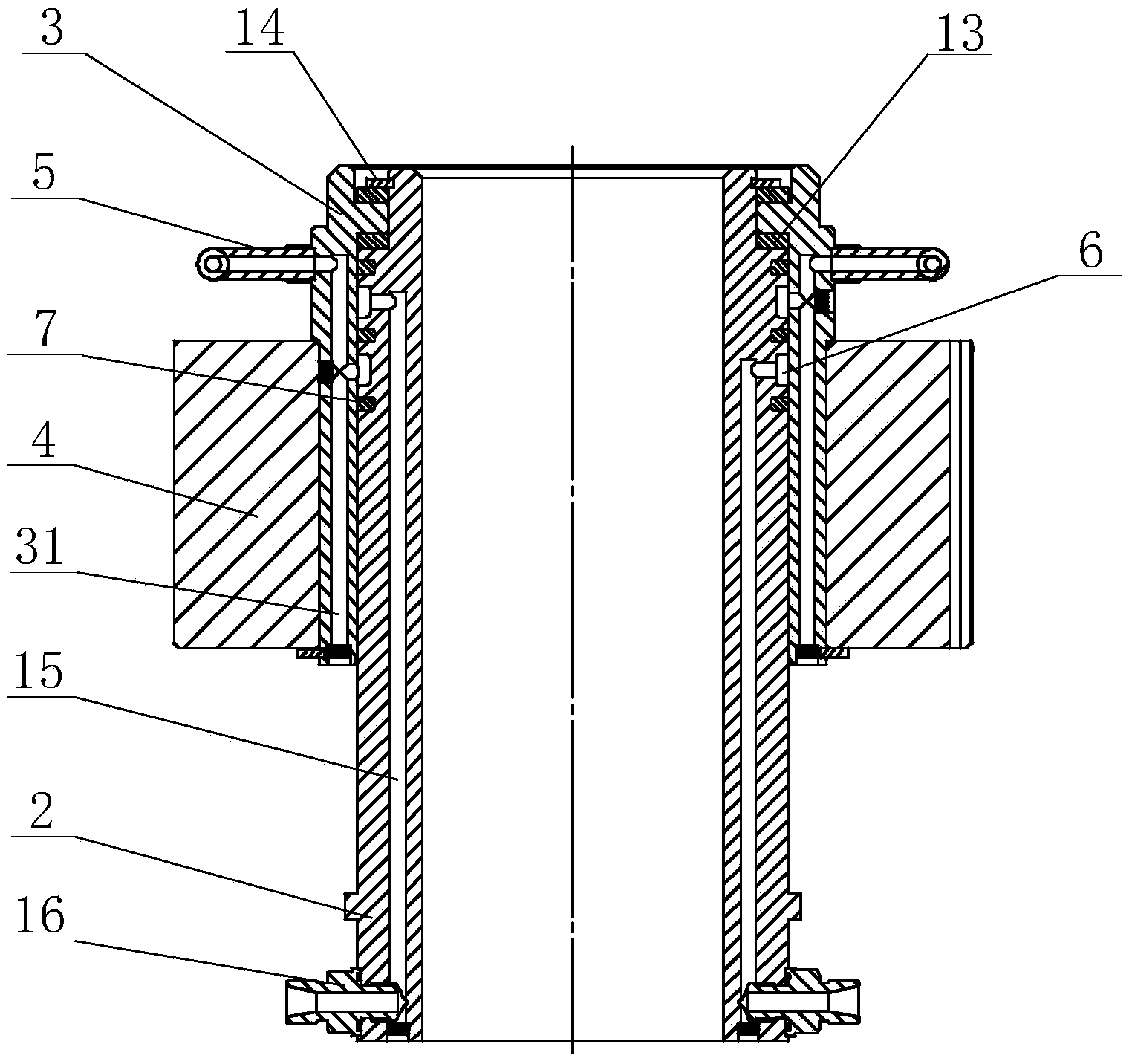
[0029] like figure 1 — Figure 4 Shown is embodiment 1 of the present invention: it comprises box-shaped base 1, fixed sleeve 2 fixed on box-shaped base 1, the rotating sleeve that is sleeved on the outside of fixed sleeve 2 and forms coaxial rotation with fixed sleeve 2 Cylinder 3, the gear 4 fixed on the rotating sleeve 3 (it can also be a worm gear), the puller seat 8 fixed on the rotating sleeve 3, the two slip assembly levers 11 fixed on the puller seat 8, The reverse side-by-side double floating oil cylinders that are set on the two slip assembly levers 11 and supported by two floating springs 9 and the floating pallet 10 drive the slip assembly 12, and the covers fixed on the two slip assembly levers 11 plate 22, such as figure 2 As shown, the reverse side-by-side double floating oil cylinders drive the slip assembly 12, which consists of two oil cylinders 18 placed side by side, the first slip 19 and the second slip 20 fixedly connected to the two ends of the two o...

Embodiment 2

[0033] like Figure 7 As shown, the structure is similar to that of Embodiment 1, except that a floating backing plate 25 and a spring 26 are arranged between the reverse side-by-side double floating oil cylinder drive slip assembly 12 and the cover plate 22, and the lower end of the spring 26 is in contact with the floating backing plate 25. Connection, the upper end of the spring 26 is connected with the cover plate 22, so that the slip assembly 12 driven by the reverse parallel double floating oil cylinder can float up and down in both directions.

Embodiment 3

[0035] like Figure 8 , 9As shown, the structure is similar to that of Embodiment 2, except that the floating spring 9 and the spring 26 are not set on the two slip assembly levers 11, but four sets of elastic support assemblies 27 are respectively fixed on the lever base 8, the described The elastic support assembly 27 includes a guide post 28, a spring 26 (or floating spring 9) is set on the guide post 28, a sleeve 29 is set outside the spring 26 (or floating spring 9), and a drag reducing device is installed on the top of the sleeve 29. The steel ball 30, under the action of the spring force, the drag-reducing steel ball withstands the floating supporting plate 10; at the same time, four groups of elastic support assemblies 27 are respectively fixed on the bottom surface of the cover plate 22, and the steel ball 30 at the lower end of the elastic support assembly 27 tops Live floating backing plate 25.


PUM


Abstract

The invention discloses a hydraulic power chuck for an automatic drilling machine. A reversed parallel floating dual-oil cylinder-driven slip assembly which is sleeved on two slip assembly poking rods and is supported by two slip assembly floating springs and floating support plates can be used for clamping or loosening a drill rod under the combined driving of two oil cylinders. A rotary sleeve and the two slip assembly poking rods fixedly arranged on the rotary sleeve are driven to rotate by a gear and a worm gear which are fixed on the rotary sleeve and the driving of a gear and a worm which are matched with the gear and the worm gear, and the slip assembly is further driven to rotate; when being clamped by the slip assembly, the drill rod is driven to rotate, so screwing and unscrewing of connection threads of two drill rods up and down are realized. The hydraulic power chuck for the automatic drilling machine is simple and compact in structure and convenient to operate, control and manufacture.

Description

technical field [0001] The invention relates to a hydraulic power chuck, in particular to a hydraulic power chuck for an automatic drilling machine. [0002] Background technique [0003] Many drilling rigs used in modern mine rock drilling and geological exploration have the function of automatically connecting and unloading drill pipes, so hydraulic or mechanical power chucks are used to clamp the drill pipe or drilling tools and unscrew the connecting thread. Most of the existing hydraulic power chucks for automatic drilling rigs are general-purpose for land drilling rigs, and they are considered to be applicable to many specifications of drilling tools, and the requirements for external dimensions are relatively loose. It is heavy and not suitable for deep hole core sampling drilling rigs with automatic loading and unloading rods working on the seabed, or small automatic drilling rigs with relatively single specifications for drilling pipes and drilling tools in narrow s...

Claims


Application Information

Patent Timeline
Patent Type & Authority Applications(China)
IPC IPC(8): E21B19/10
Inventor 黄筱军万步炎金永平
Owner HUNAN SEA BULL GEOLOGICAL EXPLORATION CO LTD
Why Eureka
Try Eureka