Reciprocating linear movement and rotational movement converter for small-semicircular gear
A technology of reciprocating linear motion and rotary motion, applied in the direction of machines/engines, mechanical equipment, etc., can solve problems such as small thrust, dead spots, and sufficient power conversion, and achieve strong thrust, reliable connection, and maximum power output. Effect
- Summary
- Abstract
- Description
- Claims
- Application Information
AI Technical Summary
Problems solved by technology
Method used
Image

Examples
Embodiment Construction
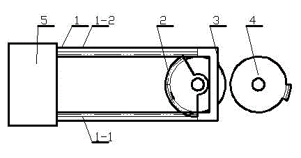
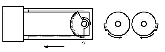
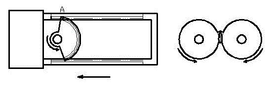
[0019] In the accompanying drawings, the reciprocating linear motion and rotary motion converter of the small semicircular gear includes a rack track 1 connected to the piston 5, and the rack track 1 is composed of two parallel upward racks 1-1 and a downward rack 1-2 structure; the rack track 1 is internally meshed with a small semicircular gear 2, and the small semicircular gear 2 is coaxially connected with a transition gear 3 with partial teeth; the rack track 1 is associated with a A sub-rack gear 4 that is partially provided with gear teeth and can be meshed with the transition gear 3 .
[0020] The arc length of the small semicircular gear 2 is less than 1 / 2 of the circumference of the addendum; the sum of the arc length of the transition gear 3 with the teeth and the arc length of the small semicircular gear 2 equals 1 / 2 of the circumference of the circle.
[0021] The radius of the addendum circle of the small semicircular gear 2 is equal to the radius of the addendu...
PUM
 Abstract
Description
Claims
Application Information
PatSnap Eureka turns technology decisions into work you can execute. Powered by our Innovation Knowledge Graph, it runs expert workflows across engineering, life sciences, materials and intellectual property. Get your review-ready output in minutes.


